Needle wire stamping die device with sawtooth tail end and stamping die method

A zigzag, needle-wire technology, applied in the field of medical devices, can solve the problems of low cost and instability

Pending Publication Date: 2019-12-20
马鞍山邦德医疗器械有限公司
View PDF1 Cites 0 Cited by
  • Summary
  • Abstract
  • Description
  • Claims
  • Application Information

AI Technical Summary

Problems solved by technology

[0005] Aiming at the problem that the connection between the needle body and the spring wire wound on the needle tail is not firm in the prior art, the present invention provides a needle wire punching device and a punching method with a zigzag tail end. The upper surface of the lower die and the The lower surface of the upper mold is adaptively provided with lower sawtooth grooves and upper sawtooth grooves in the horizontal direction, and the upper mold is adaptively pressed into the lower mold to complete the zigzag shape of the needle tail. The zigzag needle tail can It is stuck in the middle of the metal spring wire pre-wound into a spiral shape to solve the problem that the metal spring needle handle is not firm when connecting the needle body; and the device is simple and low in cost

Method used


Image

  • Needle wire stamping die device with sawtooth tail end and stamping die method
  • Needle wire stamping die device with sawtooth tail end and stamping die method
  • Needle wire stamping die device with sawtooth tail end and stamping die method

Examples


Embodiment 1

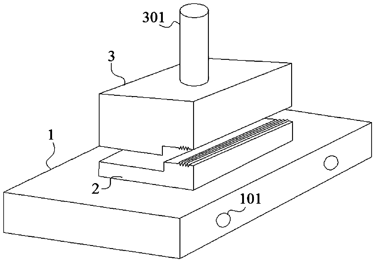
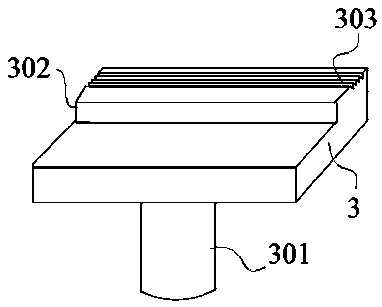
[0035] A kind of tail end of the present embodiment is a zigzag needle thread die device and die method, such as figure 1 As shown, it includes a workbench 1, a lower mold 2 and an upper mold 3. The lower mold 2 is fixedly installed on the upper surface of the workbench 1, and the front and rear surfaces of the workbench 1 are symmetrically provided with bolt holes 101. The bolts The holes 101 are matched with bolts to fix the workbench 1 and the foundation; the upper mold 3 is arranged above the lower mold 2 in an adaptive manner, and the upper surface of the lower mold 2 and the lower surface of the upper mold 3 are adapted in a transverse direction The lower sawtooth groove 202 and the upper sawtooth groove 303 are provided, the needle wire 4 to be formed is placed between the upper mold 3 and the lower mold 2, and the upper mold 3 is pressed into the lower mold 2 in an adaptive manner, In order to realize the zigzag shape of the needle tail 401 and to solve the problem tha...

Embodiment 2

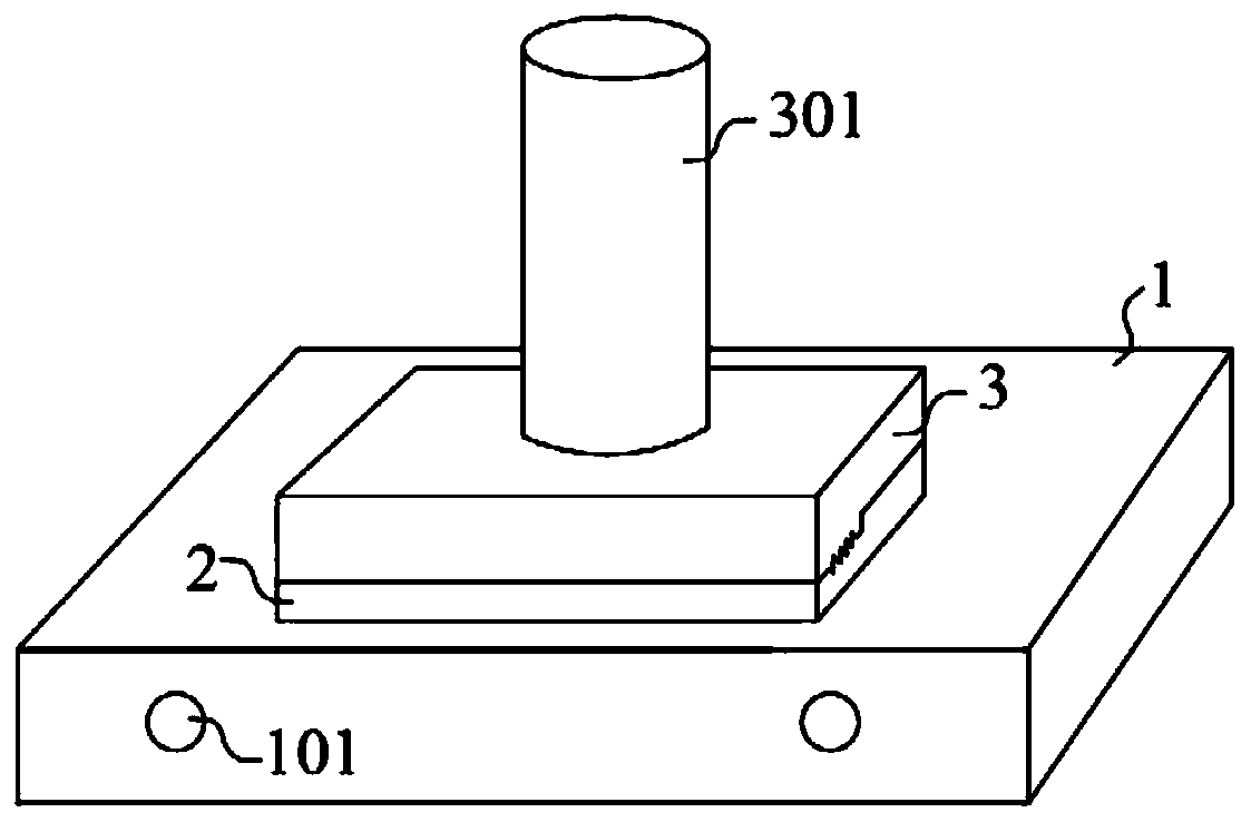
[0037] A kind of tail end of this embodiment is a zigzag needle thread die device and die method, the basic structure is the same as embodiment 1, the differences and improvements are as follows: figure 2 As shown, the middle part of the upper surface of the upper mold 3 is fixedly connected with a handle 301, and the handle 301 is fixedly connected on the outer frame of the device, and the handle 301 is connected with the lifting mechanism on the outer frame of the device, and the handle is driven up and down by the lifting mechanism. Move to realize the pressing and lifting of the upper mold 3, so as to complete the molding of the needle tail 401.

Embodiment 3

[0039] A kind of tail end of this embodiment is a zigzag needle thread die device and die method, the basic structure is the same as embodiment 2, the differences and improvements are as follows: figure 2 As shown, the middle part of the upper surface of the upper mold 3 is fixedly connected with a handle 301 , and the handle 301 is moved up and down by holding the handle 301 to realize the pressing and lifting of the upper mold 3 , thereby completing the forming of the needle tail 401 .


PUM


Abstract

The invention discloses a needle wire stamping die device with a sawtooth tail end and a stamping die method, and belongs to the field of medical devices. The needle wire stamping die device with thesawtooth end comprises a workbench, a lower die and an upper die, wherein the lower die is fixedly installed on the upper surface of the workbench, lower sawtooth grooves and upper sawtooth grooves are horizontally formed in the upper surface of the lower die and the lower surface of the upper die in a matched mode, the middle part of the upper surface of the upper die is fixedly connected with ahandle, and the lower pressure and lift of the upper die is controlled by the handle, so that a sawtooth shape of a needle tail is formed. A metal spring needle handle connection method comprises thesteps that a metal spring needle handle is wound into a spiral shape and then cut into a suitable length, then a needle wire is threaded into the spiral metal spring needle handle, and the needle handle is pulled, so that the sawtooth-shaped needle tail is tightly clamped in the middle of metal spring wires. A plastic needle handle connection method comprises the steps that the sawtooth needle wire is put into an injection mold, the injection molding is one-time molding, is closely combined with the sawtooth shape, and mass production is convenient.

Description

technical field [0001] The invention relates to the field of medical instruments, more specifically to a needle thread punching device and a punching method with a zigzag tail end. Background technique [0002] At present, the stainless steel wire flat handle needles used in traditional Chinese medicine are also called spring handle needles, and spring handle acupuncture needles are miniature medical devices. The diameter of the needle body is within 1mm, and some are even as small as 0.16mm, and the needle handle is not larger than 2mm. Therefore, the firm connection between the needle body and the needle handle has always restricted the safe operation of the industry. The conventional method is to bend the end of the needle body, and pull the curved part of the needle body into the needle handle with strong force, so that the needle body is fixed in the needle handle to achieve a certain fastness index. Although the needle body is plugged in the needle handle, because th...

Claims


Application Information

Patent Timeline
Patent Type & Authority Applications(China)
IPC IPC(8): B21D37/10B21D43/00B21D37/14
CPCB21D37/10B21D43/003B21D37/14
Inventor 王伟春
Owner 马鞍山邦德医疗器械有限公司
Why Eureka
Try Eureka