Elevator landing door system

A technology for landing doors and elevators, which is applied to elevators in buildings, fastening devices for wings, fastening devices for buildings, etc. Simple, lower installation requirements, simple effect on sill production

Inactive Publication Date: 2019-05-21
沈天宇
View PDF7 Cites 0 Cited by
  • Summary
  • Abstract
  • Description
  • Claims
  • Application Information

AI Technical Summary

Problems solved by technology

[0003] The present invention mainly solves the problems of complicated structure, high cost and high installation requirements of the landing door system in the prior art, and provides an elevator landing door system

Method used


Image

  • Elevator landing door system
  • Elevator landing door system
  • Elevator landing door system

Examples


Embodiment

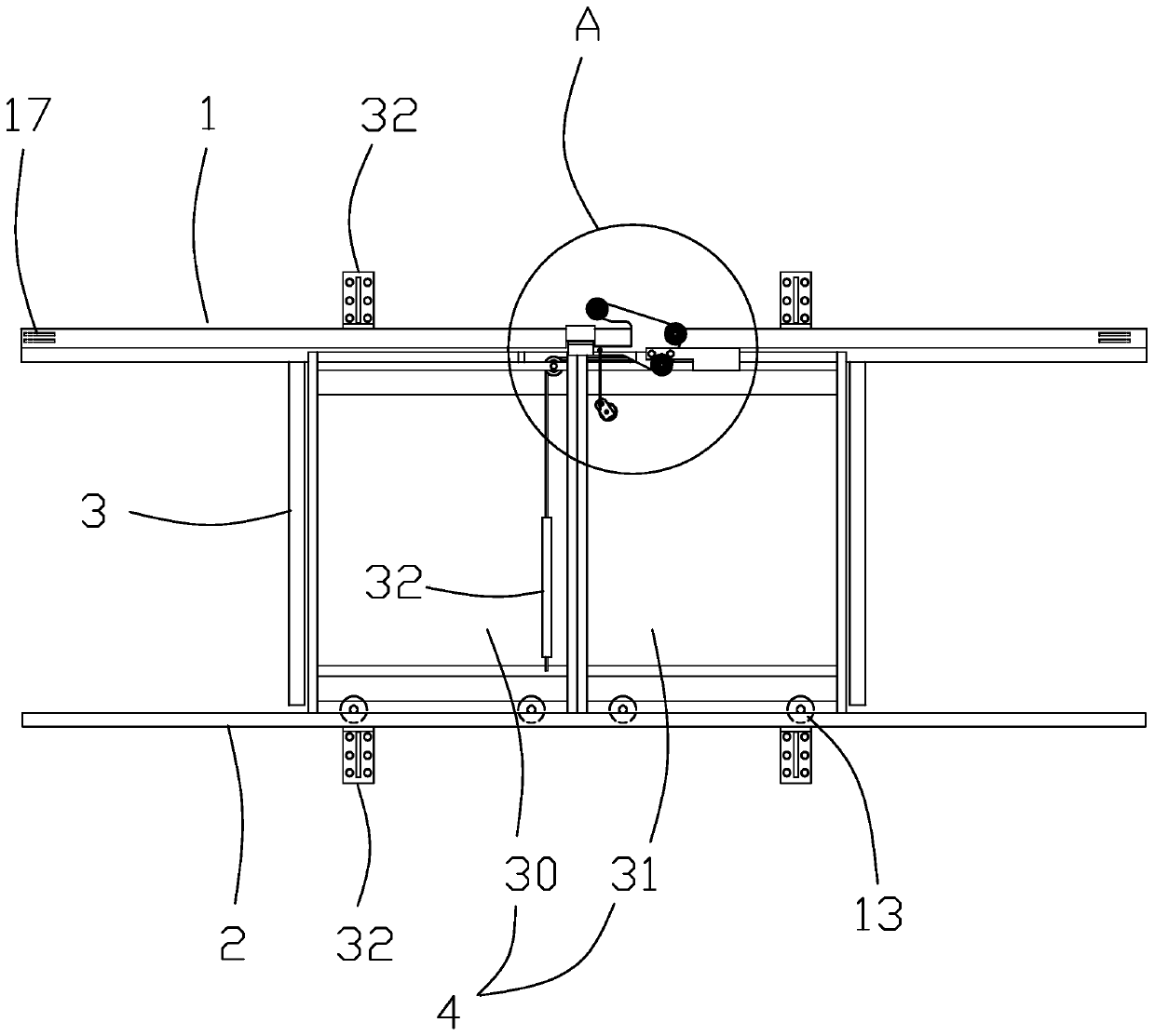
[0025] This embodiment is an elevator landing door system, such as figure 1 As shown, the upper sill 1, the sill 2, the uprights 3 arranged between the upper sill and the sill, and the left and right door panels 4. The upper sill and the sill are fixed on the hoistway wall by an L-shaped fixing frame, and the lower end of the column is fixed to the sill.

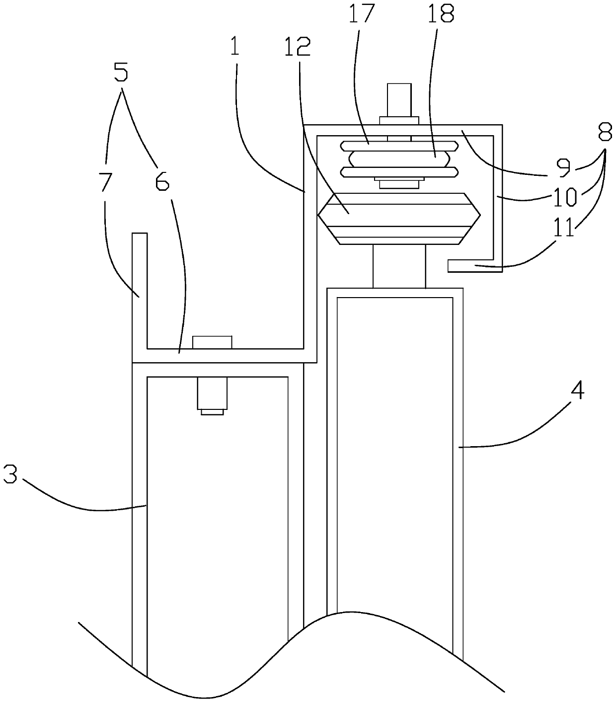
[0026] Such as figure 2 As shown, the lower end of the upper sill is bent to one side of the column to form a back plate 5. The back plate includes a fixed plate 6 and a front plate 7. The fixed plate and the front plate are perpendicularly connected to form an L-shaped structure, and the fixed plate is vertically connected to the upper sill. A blind rivet nut is built in the upper end of the column, and the fixing plate is matched with the upper end of the column and fixed by a combination bolt. The upper end of the upper sill extends and bends toward the left and right door panels to form the guide groove 8. The guide groove...


PUM


Abstract

The invention relates to an elevator landing door system. The problems of the complex structure, high cost and high installation requirement of a landing door system in the prior art are solved. The system comprises a header, a sill, upright columns, and right and left door panels, and the upright columns and the right and left door panels are arranged between the header and the sill; one side ofthe header is provided with a backplane fixed to the upright columns, and the header is located at the upper parts of the right and left door panels, and provided with a guide slot; the upper ends ofthe right and left door panels are provided with upper guide pulleys clamped in the guide slot, and the guide slot is internally provided with a steel wire rope linkage mechanism; and the right and left door panels are in linkage connection with the steel wire rope linkage mechanism, and the lower ends of the right and left door panels are provided with lower guide pulleys matched with the sill. According to the elevator landing door system, a traditional door head is cancelled, so that the structure is simpler, and the header is simple in manufacturing and more convenient in installation; theinstallation requirements are reduced, and a traditional door hanging panel is cancelled; the header plays a role in guide only, and the sill plays a role in bearing; the doo panels are moved with noneed of larger torque power, and the bearing capacity of the sill is utilized fully.

Description

Technical field [0001] The invention relates to the technical field of elevators, in particular to an elevator landing door system. Background technique [0002] The traditional elevator landing door system usually fixes the guide rail inside the upper sill or directly integrates it on the upper sill body, and realizes the hanging and sliding function of the door panel through the cooperation with the hanging plate and hanging plate wheel fixed on the door panel; the lower end of the door panel The sliding block is configured to be placed in the sill groove to realize the guiding function; the door lintel is used as a separate part to connect with the column to play a decorative role; this traditional design has a complex structure, high cost, very high installation requirements, and high surface roughness of the rail It makes the running noise louder, and the comfort is not high. The matching method of the hanging plate wheel and the guide rail increases the friction force. It i...

Claims


Application Information

Patent Timeline
Patent Type & Authority Applications(China)
IPC IPC(8): B66B13/30B66B13/06E05C19/10
Inventor 沈天宇
Owner 沈天宇
Why Eureka
Try Eureka