
Defect detection device and method for automatic repair system

A defect detection and defect technology, applied in measurement devices, optical testing flaws/defects, image enhancement, etc., can solve problems such as detection accuracy and time limitations required for detection

Active Publication Date: 2022-06-07
HB TECH CO LTD
View PDF9 Cites 0 Cited by
  • Summary
  • Abstract
  • Description
  • Claims
  • Application Information

AI Technical Summary

Problems solved by technology

[0005] As a method of inspecting glass substrate defects, visual inspection methods relying on the senses of inspectors have been widely practiced. However, this visual inspection method has limitations in inspection accuracy and time required for inspection as glass substrates become larger. sex

Method used


Image

  • Defect detection device and method for automatic repair system
  • Defect detection device and method for automatic repair system
  • Defect detection device and method for automatic repair system

Examples


Embodiment Construction

[0038] The present invention can be modified in various ways and can have various embodiments, and specific embodiments will be illustrated in the drawings and described in detail. However, the present invention is not limited to the specific embodiments, and should be understood to include all changes, equivalents, and substitutes included in the idea and technical scope of the present invention. When describing the drawings, like reference numerals are used for like components.

[0039] Terms such as first, second, A, B, etc. can be used to describe various constituent elements, but these constituent elements cannot be limited by these terms. The above terms are used only for the purpose of distinguishing one constituent element from another constituent element. For example, without departing from the scope of the claims of the present invention, a first constituent element may be named as a second constituent element, and similarly, a second constituent element may be name...


PUM


Abstract

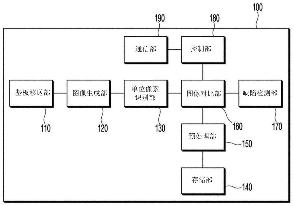
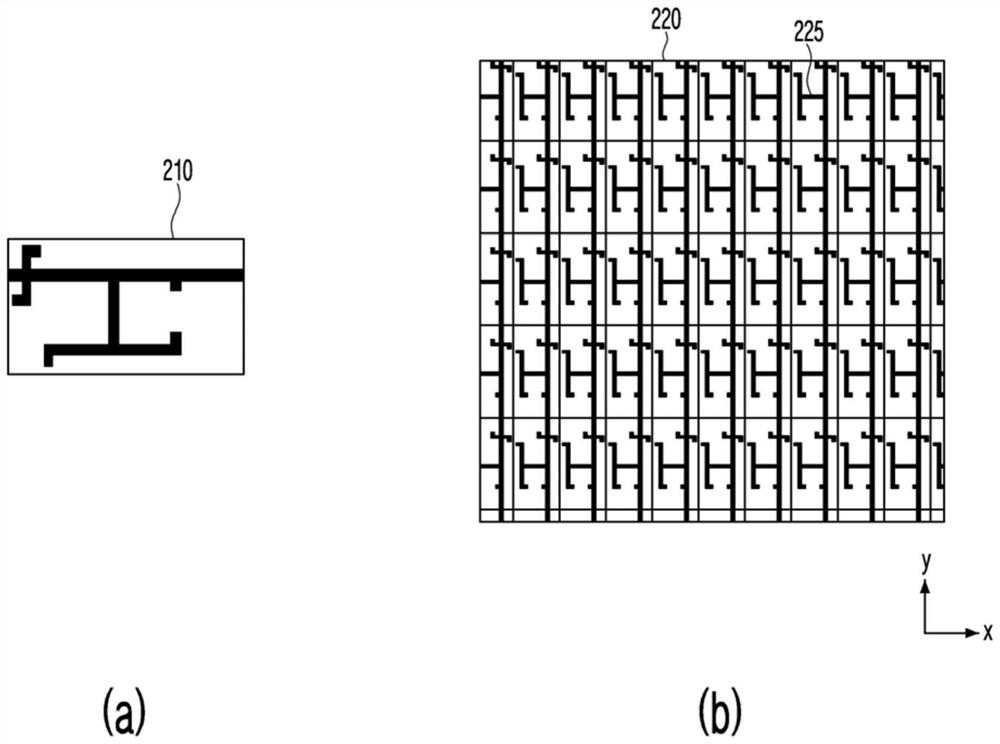
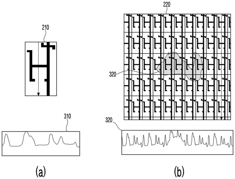
The invention discloses a defect detection device and method for a substrate. According to one aspect of the present invention, there is provided a defect detection device, which is used to detect defects of a substrate, and is characterized in that it includes: a substrate transfer part, which transfers the above-mentioned substrate along a preset direction; an image generation part, which is used to generate an image of the substrate; a unit pixel identifying unit that identifies unit pixels included in the substrate from the image of the substrate; a storage unit that stores a reference image of the unit pixel; an image comparison unit that compares the generated images of each unit pixel and The reference images stored in the storage unit are compared; the defect detection unit detects whether there is a defect in each unit pixel according to the comparison result; and the control unit is used to control each component in the defect detection device.

Description

technical field [0001] The present invention relates to an apparatus and method for detecting defects existing in a substrate in an Auto Repair System. Background technique [0002] What is described in this section merely provides background information about the present embodiments and does not constitute prior art. [0003] With the remarkable development of display equipment technology, the related technologies of various image display devices such as liquid crystal display or plasma display have been greatly improved. In particular, in an image display device that realizes large-scale and high-precision display, a high degree of technological innovation is progressing to reduce manufacturing costs and improve image quality. Glass substrates mounted on these various devices and used for displaying images are also required to have higher dimensional quality and higher-precision surface properties and conditions than ever before. When manufacturing glass for applications...

Claims


Application Information

Patent Timeline
Patent Type & Authority Patents(China)
IPC IPC(8): G01N21/88
CPCG01N21/8851G01N2021/8887Y02P40/57G06T7/001G06T7/62G06T2207/30148
Inventor 安钟植尹汝凛丁炫硕朴世景金芝珉
Owner HB TECH CO LTD
Learn More