Coiled chemical reaction tank

A chemical reaction and reaction tank technology, applied in chemical/physical/physicochemical fixed reactors, chemical instruments and methods, cleaning hollow objects, etc., can solve the problems of reaction tank corrosion, aeration head leakage, unsafety, etc. , to achieve good anti-corrosion performance, improve reaction efficiency and enhance safety

Active Publication Date: 2019-12-17
东营益盛化工有限公司
View PDF15 Cites 4 Cited by
  • Summary
  • Abstract
  • Description
  • Claims
  • Application Information

AI Technical Summary

Problems solved by technology

[0003] When chemical reaction tanks are in use, it is often necessary to gradually add different chemical raw materials to the chemical reaction tanks. Some existing chemical reaction tanks are very high, and the feed ports are all set at the top, which causes workers to be very uncomfortable during the feeding process. It is convenient, and it is unsafe to use climbing ladders to feed materials, which not only wastes the physical strength of the workers, but also brings troubles to the work of the workers. At the same time, after the reaction tank is used, the residual raw materials on the inner wall cannot be cleaned. On the inner wall, the chemical raw materials are easy to cause corrosion to the reaction tank, which reduces the service life, and there is a great safety hazard in continued use. At the same time, the existing reaction tank aeration device is mostly a bubble generating device, which generates bubbles through the bottom of the chemical reaction tank. , to speed up the reaction efficiency, the aeration head of the aeration device has been used for a long time for leakage and blockage, which requires manual cleaning and maintenance

Method used


Image

  • Coiled chemical reaction tank
  • Coiled chemical reaction tank
  • Coiled chemical reaction tank

Examples


Embodiment Construction

[0023] In order to make the technical means, creative features, goals and effects achieved by the present invention easy to understand, the present invention will be further described below in conjunction with specific embodiments.

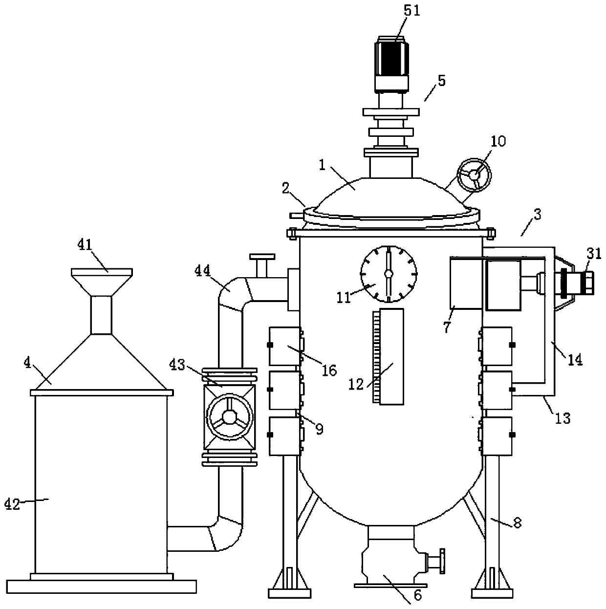
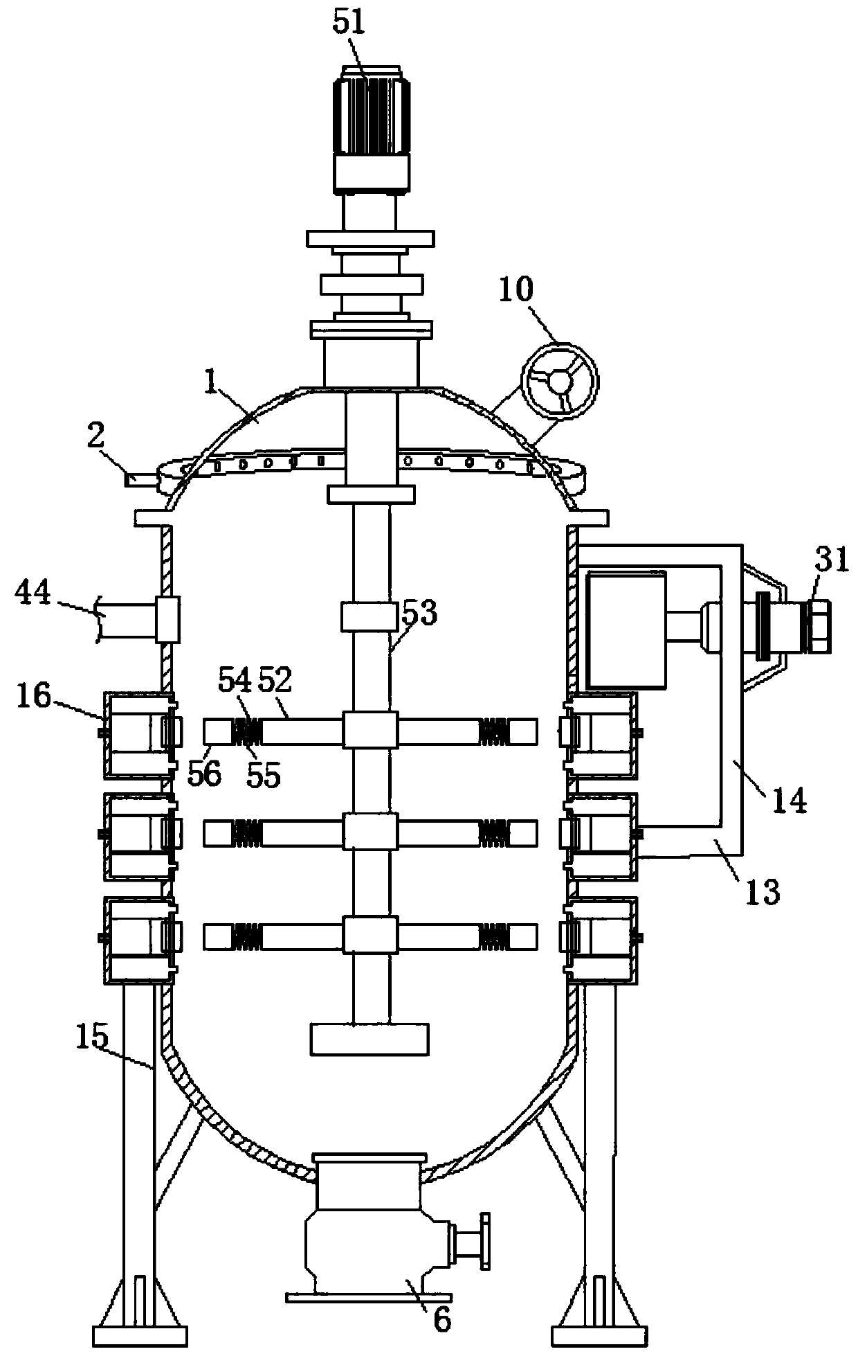
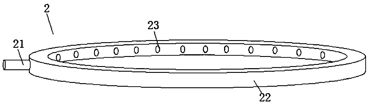
[0024] Such as Figure 1-Figure 4 As shown, a coil type chemical reaction tank of the present invention comprises a reaction tank body 1, a cleaning mechanism 2, a feeding mechanism 3, a water adding mechanism 4 and a stirring mechanism 5, and the inside of the reaction tank body 1 is provided with a stirring mechanism 5, The upper outer wall of the reaction tank body 1 is fixedly equipped with a ring-shaped cleaning mechanism 2, the cleaning mechanism 2 communicates with the inner wall of the reaction tank body 1, and both sides of the outer wall of the reaction tank body 1 are fixed and installed by bolts. There is a support column 8, a rubber pad 9 is arranged between the support column 8 and the reaction tank body 1, a support plate 13 is fixe...


PUM


Abstract

The invention relates to the field of reaction tanks, and concretely relates to a coiled chemical reaction tank. The coiled chemical reaction tank comprises a reaction tank body, a cleaning mechanism,a feeding mechanism, a water adding mechanism and a stirring mechanism, a stirring mechanism is arranged in the reaction tank body, the annularly arranged cleaning mechanism is fixedly mounted on theouter wall of the upper end of the reaction tank body, the cleaning mechanism is communicated with the inner wall of the reaction tank body; supporting columns are fixedly mounted at two sides of theouter wall of the reaction tank body through bolts, a rubber pad arranged between every supporting column and the reaction tank body, and a supporting plate is fixedly mounted at one side of the reaction tank body. The cleaning mechanism, a water inlet tube, a water spray tube and a spray head are used cooperatively to realize the flushing of the residual raw material on the inner wall of the reaction tank body, so after the use of the reaction tank is used, a cleaning solution is added through the water inlet tube, enters the annularly-arranged water spray tube, and is sprayed out through the spray head on the water spray tube to flush the chemical raw material on the sidewall of the inner cylinder of the reaction tank body, so the inner sidewall of the tank body is kept clean, and can be easily used next time.

Description

technical field [0001] The invention relates to the field of reaction tanks, in particular to a coil type chemical reaction tank. Background technique [0002] The reaction tank is a chemical reaction and physical reaction vessel, which is divided into pressure vessel and normal pressure vessel. It is widely used in petroleum, chemical industry, food, medicine, pesticide, scientific research and other industries. It is used to complete polymerization, condensation, vulcanization, alkylation, Chemical processes such as hydrogenation, and reaction equipment for many processes of organic dyes and intermediates. [0003] When chemical reaction tanks are in use, it is often necessary to gradually add different chemical raw materials to the chemical reaction tanks. Some existing chemical reaction tanks are very high, and the feed ports are all set at the top, which causes workers to be very uncomfortable during the feeding process. It is convenient, and it is unsafe to use climbi...

Claims


Application Information

Patent Timeline
Patent Type & Authority Applications(China)
IPC IPC(8): B01J19/18B08B9/093
CPCB01J19/18B08B9/093
Inventor 郑豪张孟孟胡琴
Owner 东营益盛化工有限公司
Why Eureka
Try Eureka