Novel slurry stirring device
A stirring device and slurry technology, which is applied in the direction of mixer accessories, transportation and packaging, dissolution, etc., can solve the problems of damage, stirring dead angle, slurry settlement, etc., and achieve the effects of fully and evenly stirring, improving use efficiency, and saving investment
- Summary
- Abstract
- Description
- Claims
- Application Information
AI Technical Summary
Problems solved by technology
Method used
Image
Examples
Embodiment 1
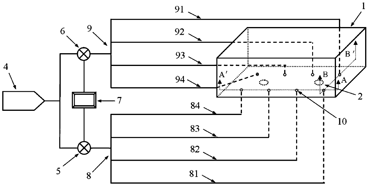
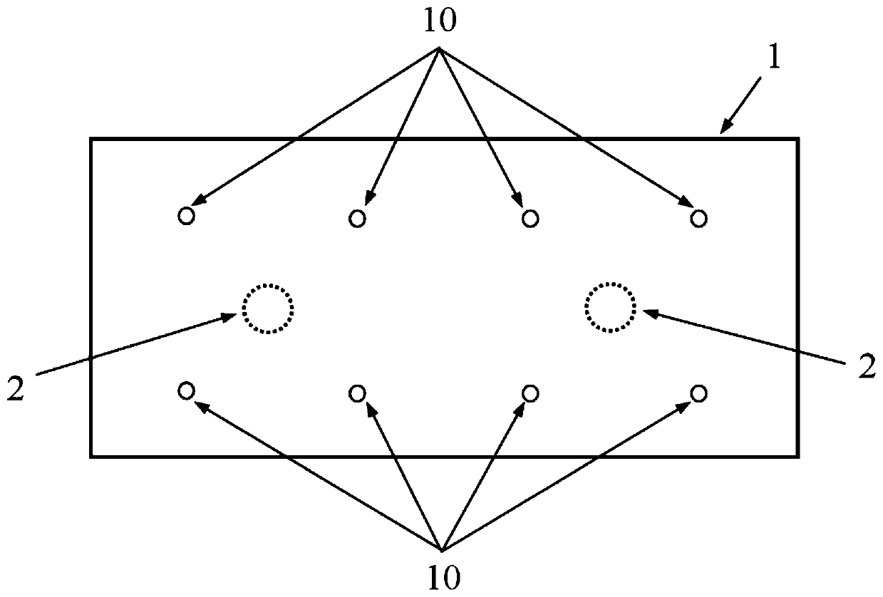
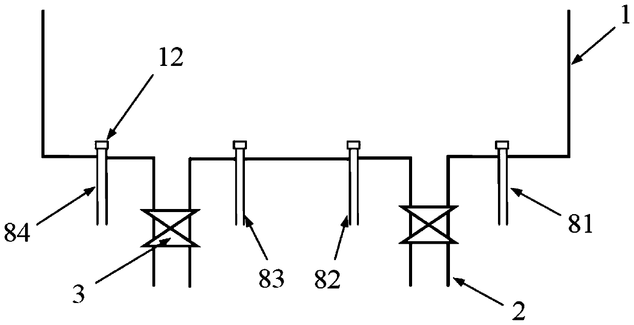
[0037] Such as Figures 1 to 4 As shown, a new slurry stirring device includes a stirring tank 1, a slurry discharge pipe 2 and a slurry discharge valve 3, the slurry discharge pipe 2 is connected through the bottom of the stirring tank 1, an air compressor 4, and a first electric control valve 5 , the second electronically controlled valve 6, the PLC controller 7, the first group of high-pressure air pipes 8, the second group of high-pressure air pipes 9, and the jet head-10 connected to one end of the first group of high-pressure air pipes 8 and the second group of high-pressure air pipes 9;
[0038] The first group of high-pressure air pipes 8 and the second group of high-pressure air pipes 9 are connected to the air compressor 4 through the first electric control valve 5 and the second electric control valve 6 respectively;
[0039] The PLC controller 7 is connected to the first electric control valve 5 and the second electric control valve 6, and alternately controls the ...
Embodiment 2
[0047] Such as Figure 5 As shown, on the basis of Example 1, the stirring effect is further optimized, and several side wall high-pressure air pipes 13 are connected to the front wall and the rear wall of the stirring tank 1, and the side wall high-pressure air pipes connected to the front wall of the stirring tank 1 13 The air inlet end is connected with the first electric control valve 5, and the side wall high-pressure gas pipe 13 which is connected to the rear wall of the stirring tank 1 is connected with the second electric control valve 6.
[0048] Further, the side wall high-pressure air pipe 13 is connected to the end of the stirring tank 1 connected with the second nozzle 11, and the direction of the second nozzle 11 is inclined upward with respect to the plane of the side wall of the stirring tank 1.
[0049] The above-mentioned arrangement of several sidewall high-pressure air pipes on the sidewall of the stirring tank further accelerates the flow velocity of the s...
Embodiment 3
[0051] Such as Figures 1 to 5 As shown, on the basis of Embodiments 1 and 2, further, the first nozzle 10 and the second nozzle 11 are provided with a check valve 12 to prevent the slurry from flowing back into the high-pressure air pipe.
[0052] During normal operation, under the action of high-pressure gas, the slurry cannot enter the high-pressure air pipe, but when the stirring is stopped, the slurry will flow into the high-pressure air pipe, which will easily cause blockage after a long time, so setting a check valve can effectively prevent The slurry flows back into the high-pressure gas pipe.
[0053] Further, the inclination angle between the air jet head 10 and the bottom plane of the stirring tank 1 is 20°-70°, and the inclination angle between the air jet head two 11 and the side wall plane of the stirring tank 1 is 20°-70°.
[0054] In actual use, the above-mentioned inclination angle will be adjusted and determined according to the size of the stirring tank, th...
PUM
 Abstract
Description
Claims
Application Information
 - R&D Engineer
- R&D Manager
- IP Professional
- Industry Leading Data Capabilities
- Powerful AI technology
- Patent DNA Extraction
Browse by: Latest US Patents, China's latest patents, Technical Efficacy Thesaurus, Application Domain, Technology Topic, Popular Technical Reports.
© 2024 PatSnap. All rights reserved.Legal|Privacy policy|Modern Slavery Act Transparency Statement|Sitemap|About US| Contact US: help@patsnap.com


