Anti-shake effect test method and device, electronic equipment and medium
An effect testing and anti-shake technology, which is applied to TVs, electrical components, color TVs, etc., can solve the problems of poor test accuracy and affect the analysis accuracy of test charts, so as to ensure the detection accuracy and avoid inaccuracy.
- Summary
- Abstract
- Description
- Claims
- Application Information
AI Technical Summary
Problems solved by technology
Method used
Image
Examples
Embodiment 1
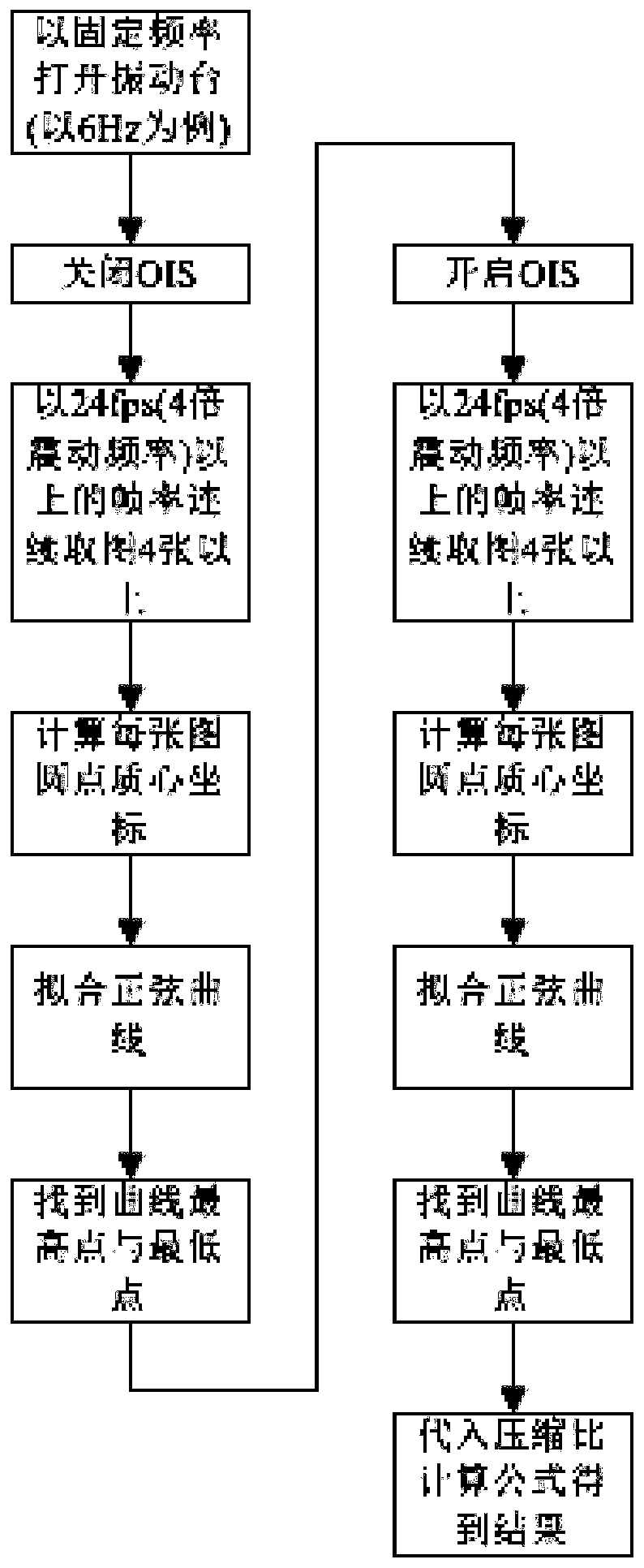
[0042] This embodiment provides a method for testing the anti-shake effect, please refer to figure 2 , figure 2 It is a flow chart of the anti-shake effect testing method in the embodiment of the present invention, including:
[0043] Step S201, in the vibrating state, the camera module turns on the anti-shake function and captures N opened test pictures of the test target; N is an integer greater than 1;
[0044] Step S202, in the vibration state, the camera module turns off the anti-shake function and captures M closed test pictures of the test target; M is an integer greater than 1;
[0045] Step S203, comparing the imaging position of the test object in the N open test images with the imaging position of the test object in the M closed test images to determine the anti-shake effect.
[0046] It should be noted that the execution order of step S201 and step S202 is not limited, step S201 may be executed first, and step S202 may also be executed first.
[0047] Below, c...
Embodiment 2
[0075] like Figure 4 As shown, an anti-shake effect test device is provided, including:
[0076] The opening module 401 is used to enable the camera module to open the anti-shake function and capture N pieces of open test charts of the test target under the vibration state; N is an integer greater than 1;
[0077] Closing module 402, for under vibrating state, camera module closes anti-shake function and photographs and obtains M pieces of closed test charts of said test target; M is an integer greater than 1;
[0078] The comparison module 403 is configured to compare the imaging position of the test target in the N open test pictures with the imaging position of the test target in the M closed test pictures to determine the anti-shake effect.
[0079] In the embodiment of the present application, the anti-shake effect test device may be a camera module, a computer, a dedicated tester or a test device integrated into a production line, which is not limited here.
[0080] S...
Embodiment 3
[0083] like Figure 5As shown, the present embodiment provides an electronic device, including a memory 510, a processor 520, and a computer program 511 stored on the memory 510 and operable on the processor 520. When the processor 520 executes the computer program 511 Implement the following steps:
[0084] In the vibration state, the camera module turns on the anti-shake function and takes N pieces of open test pictures of the test target; N is an integer greater than 1;
[0085] In the vibrating state, the camera module closes the anti-shake function and captures and obtains M pieces of closed test diagrams of the test target; M is an integer greater than 1;
[0086] Comparing the imaging position of the test target in the N open test pictures with the imaging position of the test target in the M closed test pictures to determine the anti-shake effect.
[0087] In this embodiment of the present invention, when the processor 520 executes the computer program 511, any imple...
PUM
 Abstract
Description
Claims
Application Information
 - R&D
- Intellectual Property
- Life Sciences
- Materials
- Tech Scout
- Unparalleled Data Quality
- Higher Quality Content
- 60% Fewer Hallucinations
Browse by: Latest US Patents, China's latest patents, Technical Efficacy Thesaurus, Application Domain, Technology Topic, Popular Technical Reports.
© 2025 PatSnap. All rights reserved.Legal|Privacy policy|Modern Slavery Act Transparency Statement|Sitemap|About US| Contact US: help@patsnap.com


