Motor rotor and synchronous reluctance motor

A technology of motor rotor and rotor core, which is applied to synchronous motors, electrical components, electromechanical devices, etc. for single-phase current, can solve the problem of weakening the amplitude of the air gap magnetic density, the decrease of motor output torque, and the operation performance of the motor. It can optimize the air gap magnetic density, improve the salient pole ratio, and increase the stator and rotor air gap.

Active Publication Date: 2019-12-13
GREE ELECTRIC APPLIANCES INC
View PDF8 Cites 2 Cited by
  • Summary
  • Abstract
  • Description
  • Claims
  • Application Information

AI Technical Summary

Problems solved by technology

[0003] A synchronous reluctance motor is provided in the prior art, and the rotor of the motor is provided with multiple tangent planes in the outer circumferential direction. The problem is that the distance between the tangent planes and the outer circle, that is, the width of the section between the tangent plane and the outer circle of the rotor will increase. Increase the air gap at this position, a larger air gap will weaken the amplitude of the air gap flux density, resulting in a sharp drop in the output torque of the motor, and at the same time increase the torque ripple, resulting in a decrease in the performance of the motor

Method used


Image

  • Motor rotor and synchronous reluctance motor
  • Motor rotor and synchronous reluctance motor
  • Motor rotor and synchronous reluctance motor

Examples


Embodiment Construction

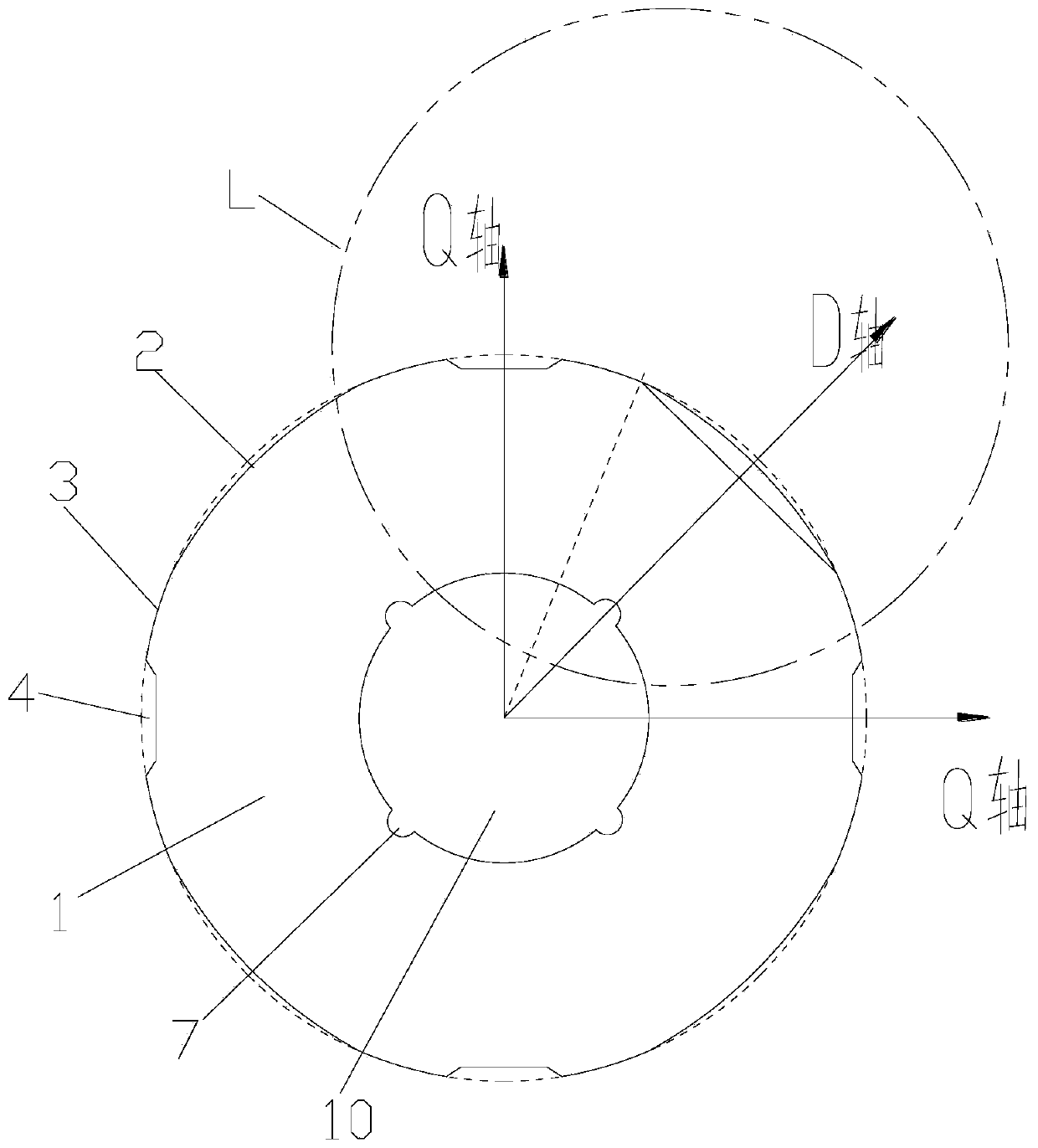
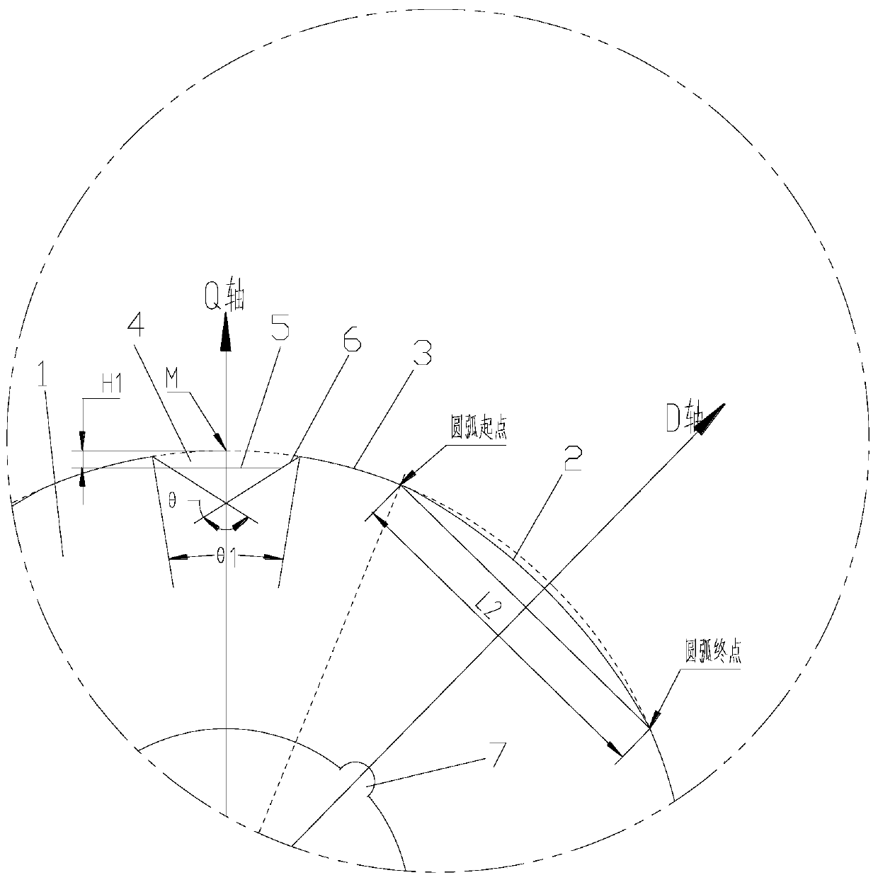
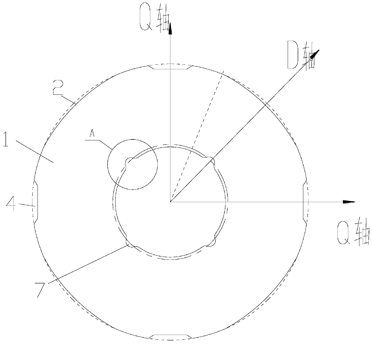
[0029] see in conjunction Figure 1 to Figure 8 As shown, according to the embodiment of the present application, the motor rotor includes a rotor core 1. On a section perpendicular to the central axis of the rotor core 1, the outer peripheral side of the rotor core 1 has an inwardly deflected arc 2, and the inwardly deflected arc 2 is located on the D axis, and the inward arc 2 is located between the largest outer circle 3 of the rotor core 1 and the chord of the inward arc 2 .

[0030] The motor rotor of the present application adopts an inwardly deflected circular arc structure on the outer circumference of the rotor core 1 located on the D axis, which can increase the stator-rotor air gap, optimize the air gap flux density in the D-axis direction, and effectively improve the synchronous reluctance motor in operation. The saliency ratio in the process increases the electromagnetic torque, and at the same time, it can avoid the air gap being too large and weaken the amplitud...


PUM

PropertyMeasurementUnit
Radiusaaaaaaaaaa

Abstract

The invention provides a motor rotor and a synchronous reluctance motor. The motor rotor comprises a rotor core (1). On a cross section perpendicular to the center axis of the rotor core (1), an inward arc (2) is on the outer circumferential side of the rotor core (1). The inward arc (2) is on the D axis. The inward arc (2) is located between the maximum outer circle (3) of the rotor core (1) andthe chord of the inward arc (2). According to the motor rotor provided by the invention, the salient pole ratio of the synchronous reluctance motor during operation can be effectively improved; electromagnetic torque can be increased; and torque ripple and iron loss can be reduced at the same time.

Description

technical field [0001] The present application relates to the field of motor technology, in particular to a motor rotor and a synchronous reluctance motor. Background technique [0002] There are no permanent magnets, squirrel cages or coils in the rotor of synchronous reluctance motors. Using the principle of minimum reluctance that the magnetic flux always closes along the path of minimum reluctance, by alternately arranging multi-layer magnetic conduction channels and air magnetic barriers in the rotor, a The inductance difference between the d-axis and the q-axis generates torque for work. The greater the inductance difference between the d-axis and the q-axis, the greater the torque density obtained. [0003] A synchronous reluctance motor is provided in the prior art, and the rotor of the motor is provided with multiple tangent planes in the outer circumferential direction. The problem is that the distance between the tangent planes and the outer circle, that is, the w...

Claims


Application Information

Patent Timeline
IPC IPC(8): H02K1/22H02K19/02
CPCH02K1/22H02K19/02H02K2213/03
Inventor 王勇胡余生卢素华陈彬黎永材李扬
Owner GREE ELECTRIC APPLIANCES INC
Why Eureka
Try Eureka