
Proton exchange membrane fuel cell combined heat and power system

A proton exchange membrane, fuel cell technology, applied in fuel cells, fuel cell additives, heating systems, etc., to achieve the system's environmental friendliness, good economy and market potential, and reduce peak loads.

Inactive Publication Date: 2019-12-13
HARBIN BOILER
View PDF4 Cites 2 Cited by
  • Summary
  • Abstract
  • Description
  • Claims
  • Application Information

AI Technical Summary

Problems solved by technology

[0003] In order to solve the existing technical problems, the present invention further provides a proton exchange membrane fuel cell combined heat and power system

Method used


Image

  • Proton exchange membrane fuel cell combined heat and power system

Examples


Embodiment 1

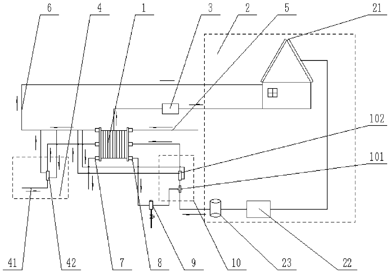
[0016] Example 1: Combining figure 1 Describe this embodiment, a proton exchange membrane fuel cell combined heat and power system, including: stack 1, hydrogen production device 2, power converter 3, air humidifier 4, cooling water pipe 5, heat supply pipeline 6, air exhaust Port 7, hydrogen outlet 8, gas-water separator 9 and injection humidification device 10, the cooling water inlet of the electric stack 1 is connected with a cooling water pipe 5, and the cooling water enters the electric stack 1 through the cooling water pipe 5, and the outlet of the electric stack 1 The water port provides heating for the user through the heating pipeline 6, the air humidifier 4 injects air into the cathode end of the cell stack 1 through the pipeline, the hydrogen production device 2 is connected with the injection humidification device 10 through the pipeline, and the injection humidification device 10 supplies air to the battery. The anode end of stack 1 is injected with hydrogen, the...

Embodiment 2

[0017] Embodiment 2: This embodiment is described in conjunction with Embodiment 1. The hydrogen production device 2 includes a solar plate 21, a water electrolyzer 22 and a hydrogen buffer tank 23. The solar plate 21 is connected to the water electrolyzer 22 through a line, and the water electrolyzer 22 The gas outlet of the hydrogen buffer tank 23 is connected to the gas inlet of the hydrogen buffer tank 23 through a pipeline, and the gas outlet of the hydrogen buffer tank 23 is connected to the injection humidification device 10 through a pipeline, and the hydrogen generated by the electrolysis of water is pressed into the hydrogen buffer tank 23 through a hydrogen compressor , both ends of the hydrogen buffer tank 23 are provided with valves and pressure gauges at the inlet and outlet. In this way, solar photoelectric electrolysis of water is used to produce hydrogen during the day, and the hydrogen is stored in the hydrogen buffer tank 23. At night, the peak power consumpti...

Embodiment 3

[0018] Embodiment 3: This embodiment is described in conjunction with Embodiments 1 to 2. The ejector humidifier 10 includes an ejector 101 and a No. 1 humidifier 102. The gas outlet of the hydrogen buffer tank 23 is connected to the high-pressure fluid inlet of the ejector 101 through a pipeline. , the outlet of the ejector 101 is connected to the inlet of the No. 1 humidifier 102 through the pipeline, and the outlet of the No. 1 humidifier 102 is connected to the anode end of the electric stack 1 through the pipeline. In this way, the use of the ejector 101 reduces the traditional circulation pump belt coming parasitic power.


PUM


Abstract

The invention discloses a proton exchange membrane fuel cell combined heat and power system, and belongs to the technical field of fuel cells. The system is characterized in that a cooling water inletof a galvanic pile is connected with a cooling water pipe, a water outlet of the galvanic pile supplies heat to a user through a heat supply pipeline, an air humidifying device injects air into the cathode end of the galvanic pile through a pipeline, a hydrogen production device is connected with an ejection humidifying device through a pipeline, the ejection humidifying device injects hydrogen into the anode end of the galvanic pile, a hydrogen exhaust port is connected with a gas-water separator through a pipeline, a gas outlet of the gas-water separator is connected with the ejection humidifying device, the galvanic pile is connected with a power supply converter through a circuit, and the power supply converter converts direct current into alternating current to supply power to the user. According to the invention, solar energy is used for photoelectrically electrolyzing water to produce hydrogen in the daytime, hydrogen stored in a buffer tank in the daytime can be used for generating electricity at the electricity utilization peak at night, the optimal working temperature of the cooling water pipe and the galvanic pile is set to be 80 DEG C, cooling water for keeping the optimal working condition of the galvanic pile is used for supplying heat to users, and the gradient utilization rate of energy is increased.

Description

technical field [0001] The invention relates to the technical field of fuel cells, in particular to a proton exchange membrane fuel cell combined heat and power system. Background technique [0002] At present, the working principle of the fuel cell combined heat and power system is that hydrogen is passed into the anode side of the fuel cell, and the air is heated by the air preheater and then passed into the cathode side of the fuel cell. Hydrogen and air undergo an electrochemical reaction in the fuel cell, and the direct current generated by the reaction is converted into alternating current by the power converter for use by users. Excess tail gas from the anode and cathode of the fuel cell enters the burner for combustion, and part of the heat generated by the combustion is supplied to the air preheater, and the remaining heat is used for hot water or heating. The current combined heat and power technology consumes a large amount of natural gas, and at the same time bu...

Claims


Application Information

Patent Timeline
Patent Type & Authority Applications(China)
IPC IPC(8): H01M8/0656H01M8/0662H01M8/04029H01M8/04082H01M8/04701H01M8/2457H01M8/2465F24D15/00
CPCF24D15/00F24D2200/19H01M8/04029H01M8/04201H01M8/04701H01M8/0656H01M8/0662H01M8/2457H01M8/2465Y02E60/50
Inventor 于强祝令昆关靖宇季鹏王禹朋
Owner HARBIN BOILER
Learn More