Kitchen range burner
A technology for burners and stoves, applied in the direction of burners, gas fuel burners, combustion methods, etc., can solve the problems of heat loss and low heating efficiency, and achieve the effect of improving combustion efficiency, improving thermal efficiency, and ensuring continuous heating
- Summary
- Abstract
- Description
- Claims
- Application Information
AI Technical Summary
Problems solved by technology
Method used
Image
Examples
Embodiment 1
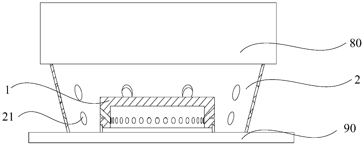
[0045] Such as figure 1 As shown, the present invention discloses a cooker burner. The cooker burner includes a fire cover 1 and an energy-gathering inner ring 2. The energy-gathering inner ring 2 is set around the fire cover 1. The energy-gathering inner ring 2 is set on the cooker table 90 Above, the energy-gathering inner ring 2 extends upwards and is in full contact with the bottom of the pot 80. A plurality of smoke outlets 21 are arranged at intervals on the outer peripheral surface of the energy-gathering inner ring 2, and the smoke outlets 21 are far away from the bottom of the energy-gathering inner ring 2 top set.
[0046] The cooker burner attaches the top of the energy-gathering inner ring 2 to the bottom surface of the pot 80, and sets the smoke outlet 21 at a position away from the top of the energy-gathering inner ring 2, so that the combustion in the energy-gathering inner ring 2 generates The flue gas gathers in the space surrounded by the bottom surface of t...
Embodiment 2
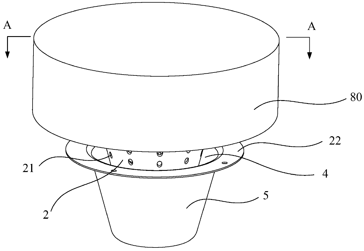
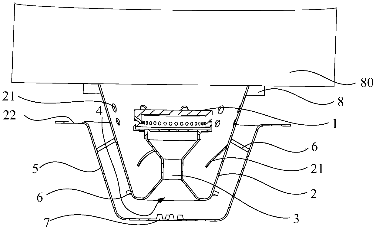
[0048] Such as figure 2 and image 3 As shown, the structure of this embodiment is basically the same as that of Embodiment 1, the difference being that: the stove burner also includes an injection tube 3 and a fire cover 1, and the injection tube 3 and the fire cover 1 are arranged in sequence along the gas flow direction, The injection pipe 3 is vertically arranged and located below the fire cover 1, the wall surface of the energy-gathering inner ring 2 extends downwards and is connected to the entrance of the injection pipe 3, and the stove burner is also provided with an air intake channel 4, the air intake channel 4 Located outside the energy-gathering inner ring 2 , both ends of the air intake passage 4 communicate with the smoke outlet 21 and the inlet of the injection pipe 3 respectively.
[0049] In this embodiment, the stove burner can introduce the high-temperature flue gas from the exhaust port 21 into the injection pipe 3 through the air intake passage 4, and th...
Embodiment 3
[0061] This embodiment also provides a stove burner, the structure of which is roughly the same as the stove burner provided in Embodiment 2, the difference is that, as Figure 4 As shown, in the cooker burner of this embodiment, the upper edge of the energy-gathering inner ring 2 is fixedly connected to the bottom surface of the pot, that is to say, the fire cover 1, the energy-gathering inner ring 2 and the injection pipe 3 are connected to the pot 80 are directly connected together for common use.
[0062] When it is necessary to heat the pot 80, the energy-gathering inner ring 2 is placed on the connecting piece 6 connected and fixed with the energy-gathering outer ring 5, so that the connecting piece 6 forms a multi-point support for the energy-gathering inner ring 2 to maintain the stability of the overall structure .
[0063] The cooker burner with this structure is fixed on the bottom surface of the pot 80 through the combination of the energy-gathering inner ring 2, ...
PUM
 Abstract
Description
Claims
Application Information
 - R&D
- Intellectual Property
- Life Sciences
- Materials
- Tech Scout
- Unparalleled Data Quality
- Higher Quality Content
- 60% Fewer Hallucinations
Browse by: Latest US Patents, China's latest patents, Technical Efficacy Thesaurus, Application Domain, Technology Topic, Popular Technical Reports.
© 2025 PatSnap. All rights reserved.Legal|Privacy policy|Modern Slavery Act Transparency Statement|Sitemap|About US| Contact US: help@patsnap.com


