
Composite material fan blade integrating large clearance

A technology of composite materials and blowers, applied in the direction of liquid fuel engines, supporting elements of blades, mechanical equipment, etc., can solve problems such as complex execution of solutions, inappropriateness of blower blades, negative impact of blade surface state, etc.

Pending Publication Date: 2019-12-13
SAFRAN AIRCRAFT ENGINES SAS
View PDF6 Cites 1 Cited by
  • Summary
  • Abstract
  • Description
  • Claims
  • Application Information

AI Technical Summary

Problems solved by technology

[0006] However, the solution described in document EP 1 312 762 is complex to implement, has a negative impact on the surface state of the blade and is not suitable for blower blades made of fiber-reinforced composite materials

Method used


Image

  • Composite material fan blade integrating large clearance
  • Composite material fan blade integrating large clearance
  • Composite material fan blade integrating large clearance

Examples


Embodiment Construction

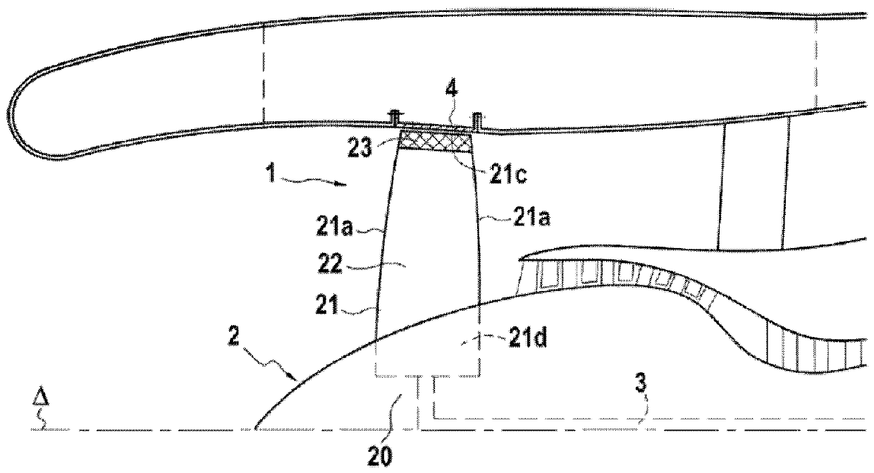
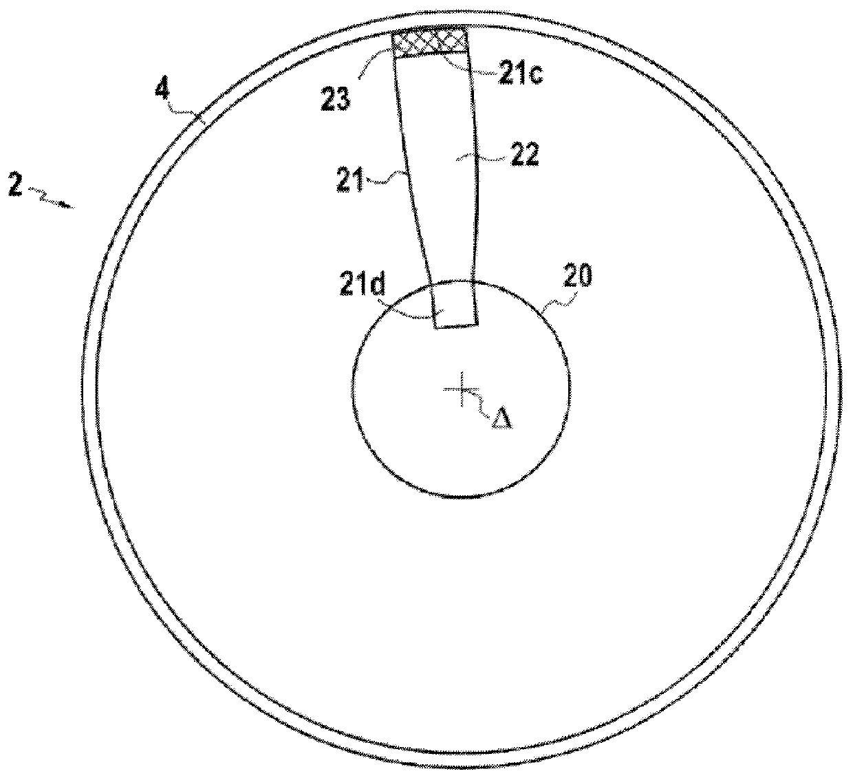
[0052] Such as figure 2 , Figure 3A with Figure 3B As shown, the turbine engine 1 has a blower 2 including a plurality of blades 21. For simplicity, a single blade 21 is shown in the figure. The blower 2 is driven by the blower shaft 3 to rotate around the axis Δ of the turbine engine 1. The blower shaft 3 may be constituted by the low pressure shaft of the turbine engine 1, or the blower shaft 3 may be driven to rotate by the low pressure shaft via a reduction gear.

[0053] The blower shaft 3 is fixed to the remaining part of the turbine engine 1 by a bearing to allow the blower shaft to rotate. Among the bearings of the fixed blower shaft 3, the turbine engine includes at least one main bearing and at least one separator bearing, the at least one separator bearing having a fracture limit lower than the limit of the at least one main bearing. Therefore, the separator bearing or each separator bearing serves as a sacrificial bearing by breaking under the effect of the imbala...


PUM


Abstract

The invention provides a composite material blade (21) for a fan (2) of a turbine engine (1). The blade (21) is characterized by including a first portion (22) that extends to the root (21d) of the blade (21) and that is made of a first material including first fiber reinforcement densified by a first matrix, the blade (21) also including a second portion (23) that extends to the tip (21c) of theblade (21) and that is made of a second material that is different from the first material and that includes second fiber reinforcement densified by a second matrix, the second material possessing abrasion resistance that is less than that of the first material.

Description

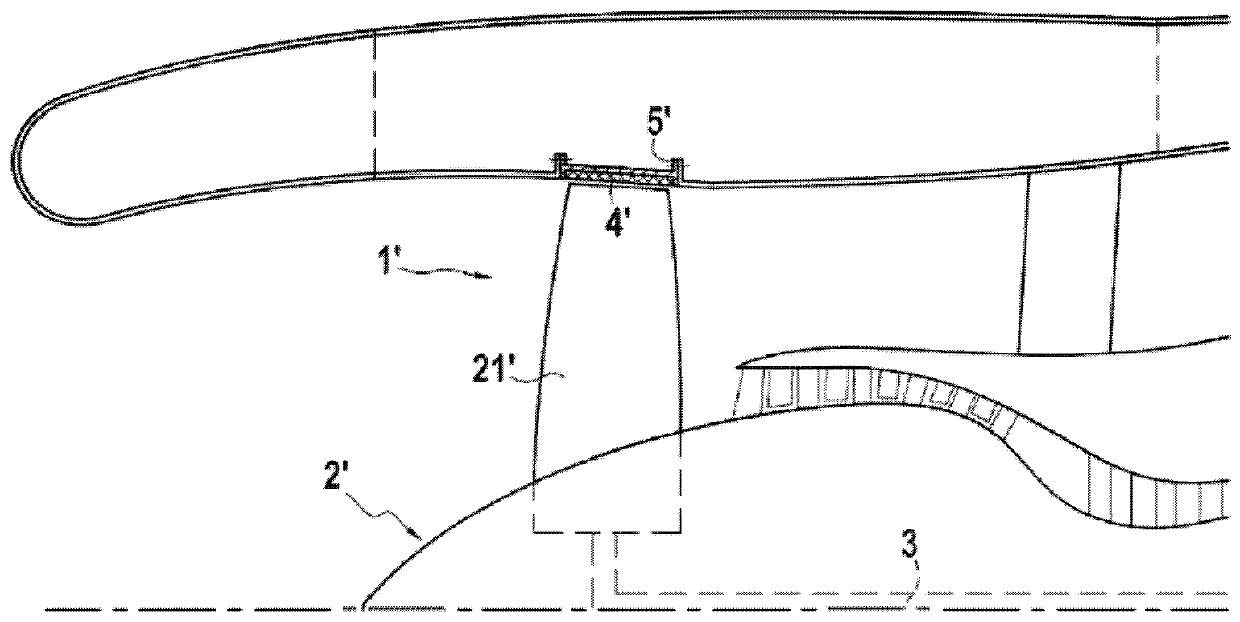
Technical field [0001] The present invention relates to the general field of aviation turbine engines, and more specifically to blowers of aviation turbine engines. Background technique [0002] As shown in FIG. 1, the aircraft turbine engine 1'includes a blower 2', which is a large-diameter propeller located at the inlet of the turbine engine, and is driven to rotate by the low-pressure shaft of the turbine engine 1'. [0003] In the case where the blade 21' of the blower 2'is lost, for example, due to foreign objects hitting the blower 2', a separator is generally provided on the blower shaft 3'to limit the rotation caused by the blower 2'when the blade 21' is lost Mechanical load caused by unbalance. The separator is a sacrificial bearing used to fix the blower shaft 3', and it is designed to break when the mechanical load becomes excessive, so as to allow the blower shaft 3'to move eccentrically, thereby limiting the application and transmission on the blower shaft 3' Mechani...

Claims


Application Information

Patent Timeline
IPC IPC(8): F04D29/38F04D29/02
CPCF04D29/388F04D29/023F01D5/282F01D11/122F01D21/045F05D2220/36F05D2240/307F05D2300/6031F05D2300/614Y02T50/60B29L2031/08B29D99/0025B29C70/0035F01D5/147F05D2230/30F05D2260/30F05D2300/603
Inventor G·德斯皮耶格勒
Owner SAFRAN AIRCRAFT ENGINES SAS
Learn More