A wrench multi-group grinding machine for hardware production and preparation

A grinding machine and wrench technology, which is applied in the direction of metal processing equipment, grinding machines, abrasive belt grinding machines, etc., can solve the problems of low grinding efficiency of grinding machines, and achieve the effects of improving grinding efficiency, increasing grinding area, and reducing blank areas

Active Publication Date: 2020-10-30
泉州西东科技有限公司
View PDF6 Cites 0 Cited by
  • Summary
  • Abstract
  • Description
  • Claims
  • Application Information

AI Technical Summary

Problems solved by technology

[0007] Aiming at the problems in the prior art, the object of the present invention is to provide a multi-group grinder for wrench for hardware production and preparation, so as to solve the technical problem of low grinding efficiency of the existing grinder

Method used


Image

  • A wrench multi-group grinding machine for hardware production and preparation
  • A wrench multi-group grinding machine for hardware production and preparation
  • A wrench multi-group grinding machine for hardware production and preparation

Examples


Embodiment 1

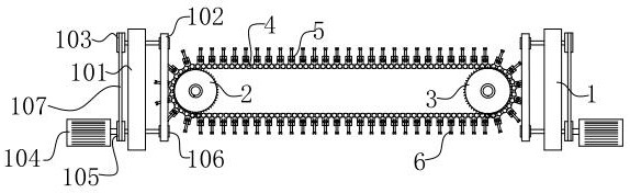
[0039] see figure 1 as well as Figure 7-10 , is a structural schematic diagram of a multi-group grinding machine with wrenches for hardware production and preparation, the grinding machine includes: a chain 4 and a grinding device 1, the chain 4 is set as a closed structure, and the inner ring of the chain 4 is provided with a first drive sprocket 2 and The second driving sprocket 3, wherein, any driving sprocket in the first driving sprocket 2 or the second driving sprocket 3 is a driving wheel, the driving chain 4 rotates, and the outer ring of the chain 4 is provided with a wrench evenly distributed to fix Platform 5, a chain sleeve 508 is respectively provided on both sides of the side wall of each wrench fixing platform 5, and the chain sleeve 508 and the wrench fixing platform are arranged as an integral structure, and the end surface of the chain sleeve 508 is provided with a through hole structure. Chain sleeve 508 is installed on the bearing pin of each chain 4, to ...

Embodiment 2

[0047] see Figure 1-10 , is a structural schematic diagram of a wrench multi-group grinding machine for hardware production and preparation. This embodiment has the same content as the above-mentioned embodiment 1, and the same will not be described in this embodiment. The specific differences are:

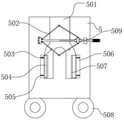
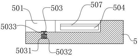
[0048] The wrench fixed table 5 is made as a square block structure, and the top surface of the wrench fixed table 5 is provided with a positioning groove 501, and a side edge of the positioning groove 501 is equipped with a deck 509, and the top surface of the wrench fixed table 5 is located at both sides of the positioning groove 501 Locking device 502 is installed, and the profile of locating groove 501 is made as the same with the profile of wrench 6 ends, and the bottom surface of locating groove 501 is equipped with spring head 503, and the both sides of locating groove 501 are respectively provided with a groove 506, groove 506 is set as a square groove, and a clamping blo...


PUM


Abstract

The invention discloses a wrench multi-group polishing machine for hardware production and manufacturing, and relates to the technical field of machining equipment. The wrench multi-group polishing machine comprises a chain and two polishing devices, wherein the chain is of a closed structure; the inner ring of the chain is provided with a first driving sprocket and a second driving sprocket; theouter ring of the chain is provided with evenly distributed wrench fixing tables; the wrench fixing tables are used for fixing wrenches to be polished; the two polishing devices are arranged at two ends of the chain; a polishing belt is arranged at the front end of each polishing device; the two polishing belts are distributed at the upper end and the lower end of the wrench fixing tables; and a machine frame is of a square plate structure. According to the wrench multi-group polishing machine, the two polishing belts are arranged, the surfaces of the two polishing belts are directly in contact with the surface of the wrench, and the upper surface and the lower surface of the wrench are simultaneously polished, therefore, the polishing area of the polishing belts is increased, and the blank non-polishing area left in each polishing process is reduced.

Description

technical field [0001] The invention relates to the technical field of mechanical processing equipment, in particular to a wrench multi-group grinding machine for hardware production and preparation. Background technique [0002] During the production process of the wrench, there will be relatively large burrs on the surface of the wrench. If it is used directly without polishing, the burrs on the surface of the wrench will easily scratch the palm of the user. [0003] At present, in the process of mass production and manufacturing of wrenches, a large number of wrenches need to be polished. Patent No. CN201620870181.8 discloses a wrench grinding machine, including a machine table, a controller, and a clamping device for clamping a wrench. As well as the grinding device for grinding the wrench, it also includes a first driving part arranged on the machine table for driving the wrench and the clamping device to rotate in the horizontal direction or to move linearly. The clamp...

Claims


Application Information

Patent Timeline
Patent Type & Authority Patents(China)
IPC IPC(8): B24B21/00B24B21/18
CPCB24B21/008B24B21/18
Inventor 林明辉
Owner 泉州西东科技有限公司
Why Eureka
Try Eureka