
Drilling equipment for machining circumferential normal hole of pipe fitting

A drilling equipment and hole processing technology, which is applied in metal processing equipment, drilling/drilling equipment, metal processing, etc., can solve the problems of inability to achieve processing effects, low hole processing efficiency, large deflection of pipe fittings, etc., to avoid pipe fittings The effect of extreme symmetry

Active Publication Date: 2019-12-13
成都新艺热缩橡塑有限公司 +1
View PDF6 Cites 7 Cited by
  • Summary
  • Abstract
  • Description
  • Claims
  • Application Information

AI Technical Summary

Problems solved by technology

[0003] In the existing drilling method, the pipe fittings are often placed in drilling machines, ironing machines and other equipment for drilling, but the hole processing efficiency of this method is low. If the surface of the pipe fittings needs to be processed in large quantities, the The processing speed is too slow, which will greatly increase the processing cost of the enterprise; now there are some special equipment that can process multiple normal holes in one clamping, but such equipment is often clamped by setting rotatable jaws at the first and last ends of the pipe Due to the lack of support for the pipe fittings at the bottom, this clamping method can only process pipe fittings with small aspect ratio (length / diameter ratio<4), small size (diameter D<200mm) pipe fittings, if the pipe fittings are larger in size (diameter D ≥200mm) or pipe fittings with a large length-to-diameter ratio (length / diameter ratio ≥4), during processing, the jaws cannot provide effective support to damage the equipment, or the pipe fittings are too long to cause large deflection during processing. Especially in the middle section of pipe fittings, resulting in the failure to achieve the desired processing effect

Method used


Image

  • Drilling equipment for machining circumferential normal hole of pipe fitting
  • Drilling equipment for machining circumferential normal hole of pipe fitting
  • Drilling equipment for machining circumferential normal hole of pipe fitting

Examples


Embodiment Construction

[0045] In order to make the purpose, technical solutions and advantages of the present invention clearer, the present invention will be further described in detail below in conjunction with the examples and accompanying drawings. As a limitation of the present invention.

[0046] Figure 1 to Figure 16 For a preferred embodiment of the present invention:

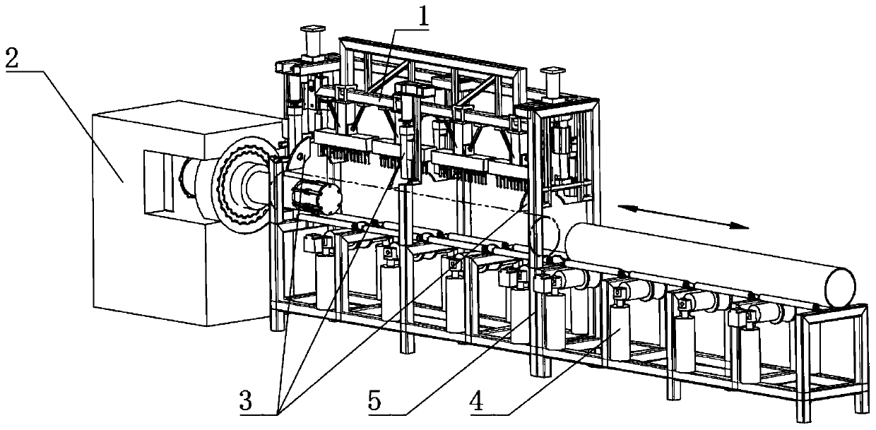
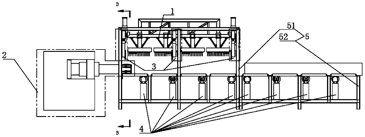
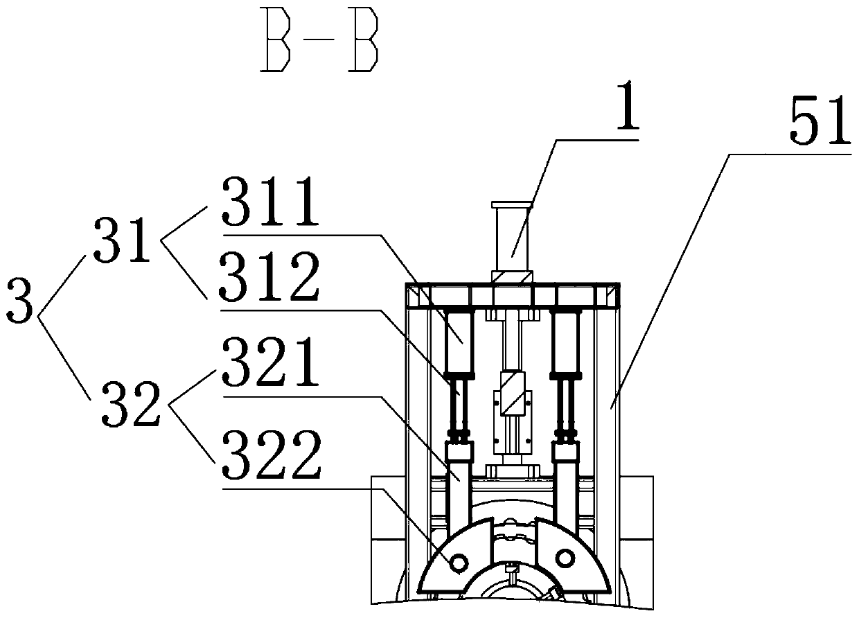
[0047] This embodiment can be used to process the drainage pipe used in the blind ditch system, assuming that the pipe fitting to be processed has a specification length×outer diameter×wall thickness=2000mm×Φ315mm×10mm. Such as figure 1 and figure 2 As shown, the device of the present application includes five major parts: a drilling module 1 , an indexing module 2 , a clamping module 3 , a feeding module 4 and a base frame 5 .

[0048] The pedestal 5 includes figure 2 The upper base frame 51 and the lower base frame 52 are shown, and the lower base frame 52 is used for placing pipe fittings and bearing loads during p...


PUM


Abstract

The invention discloses drilling equipment for machining a circumferential normal hole of pipe fitting. A first lifting module, a drilling unit body and a plurality of drill bits are arranged in an upper base frame, so that primary motion and feed motion can be achieved simultaneously, that is, a plurality of normal holes in the axial direction of the pipe fitting can be machined in the circumferential surface of the pipe fitting at one time, and the number of the normal holes can be controlled through the number of the configured drill bits; moreover, the pipe fitting can be borne and locatedby arranging a lower base frame and a radial positioning element arranged on the top surface of the lower base frame, and the situation that the symmetry degree of the pipe fitting is too poor and large deflection is generated in the machining process is avoided; and in this way, the machining quality and the machining size are guaranteed while the pipe fitting machining efficiency is guaranteed,and the drilling equipment is quite suitable for circumferential drilling of the pipe fitting and is particularly suitable for machining the pipe fitting with large specification and large length-to-diameter ratio.

Description

technical field [0001] The invention relates to the technical field of machining equipment, in particular to a drilling equipment used for machining normal holes on the peripheral surface of pipe fittings. Background technique [0002] Pipe parts are widely used in all walks of life, such as conduit parts required by engines, drainage pipes required in daily life, etc. In actual use, it is often necessary to process normal holes on the circumference of pipe fittings according to actual needs, so as to facilitate ventilation , Drainage, etc. [0003] In the existing drilling method, the pipe fittings are often placed in drilling machines, ironing machines and other equipment for drilling, but the hole processing efficiency of this method is low. If the surface of the pipe fittings needs to be processed in large quantities, the The processing speed is too slow, which will greatly increase the processing cost of the enterprise; now there are some special equipment that can pro...

Claims


Application Information

Patent Timeline
Patent Type & Authority Applications(China)
IPC IPC(8): B23B41/00B23Q3/08B23Q7/00B23Q16/02
CPCB23B41/00B23Q3/064B23Q3/08B23Q7/00B23Q16/025B23Q2703/04
Inventor 赵朝端
Owner 成都新艺热缩橡塑有限公司
Learn More