
Ascending pipe type gas rising cap for removing fine particles in sintering flue gas towers

A technology for fine particles and sintering flue gas, applied in gas treatment, dispersed particle separation, membrane technology, etc., can solve problems such as difficulty, waste, and inability to achieve ultra-low emission control of sintering flue gas, reducing processing pressure and prolonging use. Longevity and the effect of improving the uniform distribution effect

Pending Publication Date: 2019-12-13
SHANDONG GUOSHUN CONSTR GRP
View PDF0 Cites 1 Cited by
  • Summary
  • Abstract
  • Description
  • Claims
  • Application Information

AI Technical Summary

Problems solved by technology

[0003] The limestone-gypsum flue gas desulfurization technology has a fast reaction speed and a desulfurization efficiency higher than 90%. The demister layer is then discharged into the atmosphere through wet electrostatic precipitator; the sulfur dioxide is removed in the spray layer flue gas, the soluble salt and aerosol are removed in the sieve plate layer, and the mist carried by the flue gas in the mist eliminator layer After the comprehensive treatment of the above technologies, the dust content can only be reduced to about 70mg / m3, and some soluble salts and aerosols will still be entrained. It is difficult to achieve the final ultra-low emission control of sintering flue gas, and the spray slurry is easy to mix with the cleaning liquid of the sieve plate layer and the demister layer, causing a lot of waste

Method used


Image

  • Ascending pipe type gas rising cap for removing fine particles in sintering flue gas towers
  • Ascending pipe type gas rising cap for removing fine particles in sintering flue gas towers
  • Ascending pipe type gas rising cap for removing fine particles in sintering flue gas towers

Examples


Embodiment Construction

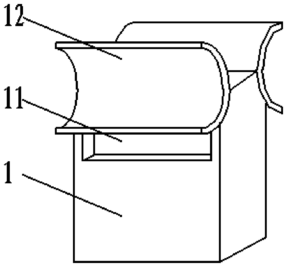
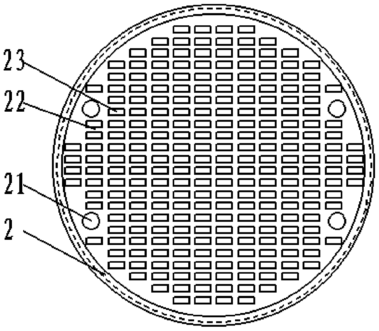
[0028] Attached below Figure 1-4 , clearly and completely describe the technical solutions in the embodiments of the present invention, obviously, the described embodiments are only some of the embodiments of the present invention, not all of them. Based on the embodiments of the present invention, all other embodiments obtained by persons of ordinary skill in the art without making creative efforts belong to the protection scope of the present invention.

[0029] In describing the present invention, it should be understood that the terms "longitudinal", "transverse", "upper", "lower", "front", "rear", "left", "right", "vertical", The orientations or positional relationships indicated by "horizontal", "top", "bottom", "inner", "outer", etc. are based on the orientations or positional relationships shown in the drawings, and are only for the convenience of describing the present invention, rather than indicating or It should not be construed as limiting the invention by imply...


PUM


Abstract

The invention discloses an ascending pipe type gas rising cap for removing fine particles in sintering flue gas towers. The ascending pipe type gas rising cap comprises a gas rising cap; the gas rising cap comprises a gas inlet, an arc-shaped blocking plate, a gas outlet, a barrel and a top plate; the gas inlet is formed in the bottom of the barrel, the arc-shaped blocking plate is arranged at thetop of the side wall of the barrel, the gas outlet is formed in the side wall of the barrel, the top plate is arranged at the top of the barrel, the gas rising cap is installed on a liquid collectingbottom plate, and the liquid collecting bottom plate is installed on the supporting frame. According to the ascending pipe type gas rising cap, the stress direction of vertical spraying liquid on thewaterproof blocking plate is changed; the problems of water leakage and liquid leakage of the gas lifting cap are solved; mixing of tower body spraying slurry with sieve plate layer and demister layer cleaning liquid can be prevented, the uniform distribution effect of the flue gas is improved, an effective gas-liquid distribution process can be formed, part of soluble salt and aerosol in the flue gas can be further removed, the stability and safety of system operation are improved, the treatment pressure of wet electric precipitation is reduced, and finally the ultralow emission standard isachieved.

Description

technical field [0001] The invention belongs to the technical field of flue gas environmental protection purification, and in particular relates to an ascending tube-type gas-rising cap for removing fine particles in a sintering flue gas tower. Background technique [0002] The removal of flue gas pollutants in the iron and steel industry has the characteristics of long process flow, many pollution production links, and large pollutant emissions; among them, sintering is the process with the largest pollutant emission in the whole process of iron and steel. According to statistics, the SO2 emitted by sintering flue gas , NOx, and PM accounted for 85%, 60%, and 40% of the total pollutant emissions in the whole process of iron and steel production; The fluctuating range of temperature (about 90-170°C) is large. How to achieve efficient and coordinated removal of sintering flue gas pollutants is the key to promoting ultra-low emissions of pollutants in the iron and steel indust...

Claims


Application Information

Patent Timeline
IPC IPC(8): B01D53/78B01D53/50
CPCB01D53/504B01D2258/0283
Inventor 仇洪波杨凤岭孟昭勤卢圣涛张振尊吕杨杨
Owner SHANDONG GUOSHUN CONSTR GRP
Learn More