
Air horn solenoid valve

A solenoid valve and air horn technology, applied in the field of solenoid valves, can solve the problems of low service life, coil open circuit, low protection level, etc., and achieve the effects of reducing product cost, prolonging service life and high production efficiency

Pending Publication Date: 2019-12-10
湖北中生汽车电器有限公司
View PDF0 Cites 0 Cited by
  • Summary
  • Abstract
  • Description
  • Claims
  • Application Information

AI Technical Summary

Problems solved by technology

[0004] One is that the protection level is low, and it is easy to enter water, resulting in coil ablation, coil open circuit, and short circuit
The reason is: there is a gap between the lead wire of the coil assembly and the rubber sleeve, and the rubber sleeve and the shell are prone to water ingress; the plastic shell and the valve seat are connected by a straight thread, which is easily deformed and cannot be sealed, resulting in water entering the valve body
[0005] Second, poor weather resistance
The reason is: because the static valve core and the valve seat are sealed by extruding the O-ring, the deformation of the sealing ring is large; the solenoid valve is connected to the valve seat through the thread of the plastic shell as a whole. Shrinkage deformation occurs, and the threaded connection becomes loose and falls off; the seal between the air seal and the moving valve core is sealed at the sharp corner of the air seal, and the sharp corner of the seal is deformed severely after being subjected to high temperature and low temperature, and the sealing effect becomes poor; this leads to the weather resistance of the solenoid valve poor sex
[0006] Third, the service life is low
[0007] Due to defects such as low protection level, poor weather resistance, and low service life, the function of the car horn cannot be used, which has a certain impact on the safety of the car and leads to instability in the performance of the vehicle. This common safety hazard has always been used by consumers. complain

Method used


Image

  • Air horn solenoid valve
  • Air horn solenoid valve
  • Air horn solenoid valve

Examples


Embodiment Construction

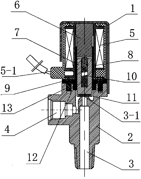
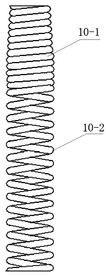
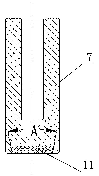
[0033] The present invention as Figure 1 to Figure 3 Shown:

[0034] An air horn solenoid valve, including a valve body, a coil assembly 5, a static valve core 6 and a moving valve core 7, wherein: the valve body includes a casing 1 and a base 2, the bottom of the base 2 is axially provided with an air outlet 3, and the air outlet The inner end of 3 is provided with a sealing end surface 3-1, the inner end of the air outlet 3 is provided with a valve core movement chamber, and the side wall of the valve core movement chamber is provided with an air inlet 4, and the air inlet 4 and the air outlet 3 move through the valve core The cavity is connected; the coil assembly 5 is located above the base 2, the coil assembly 5 includes a skeleton and a coil, the exterior of the coil assembly 5 is integrally sealed, and the lead wire 5-1 is integrated with the coil assembly 5;

[0035] A spool mounting cavity is axially provided in the frame of the coil assembly 5, and the spool mounti...


PUM


Abstract

The invention discloses an air horn solenoid valve. The air horn solenoid valve includes a valve body, a coil assembly, a static valve element and a movable valve element, wherein the valve body comprises a shell and a base, the base is provided with an air outlet, the inner end of the air outlet is provided with a valve element movement cavity, and the side wall of the valve element movement cavity is provided with an air inlet; a valve element installation cavity is formed in a coil assembly framework, the static valve element is arranged on the upper portion of the valve element installation cavity, a guide steel sleeve is arranged on the lower portion of the static valve element, the movable valve element is slidably arranged in the guide steel sleeve, the movable valve element and thestatic valve element are connected through a reset spring, an end face sealing gasket is arranged at the center of the lower end face of the movable valve element, the end face sealing gasket corresponds to a sealing end face at the inner end of an air outlet in the base, and under the action of a reset spring, the movable valve element is sealed with the sealing end face at the inner end of theair outlet of the base through the end face sealing gasket at the bottom of the movable valve element; the coil assembly and the base are connected into a whole through riveted connection with the shell. The air horn solenoid valve is simple in structure and convenient to install, and can effectively solve the defects of an existing air horn electromagnetic valve, such as low protection grade, poor weather resistance and short service life.

Description

technical field [0001] The invention relates to a solenoid valve, in particular to an air horn solenoid valve. Background technique [0002] The existing commercial vehicle air horn control solenoid valve includes a valve body, a coil assembly and a valve core, wherein: the valve core includes a moving valve core and a static valve core, the valve body includes a shell and a base, and the bottom of the base is axially provided with a stepped air outlet , the inner end of the air outlet is provided with an installation cavity, and the radial direction below the installation cavity is provided with an air inlet. The coil assembly is set on the outer edge of the base valve core installation cavity and placed on the base. The coil assembly is fixed on the base through the shell screw connection ;The upper part of the spool installation cavity is installed with a static spool, and the static spool and the base are sealed by an O-ring. The lower part of the spool installation cavi...

Claims


Application Information

Patent Timeline
Patent Type & Authority Applications(China)
IPC IPC(8): F16K1/00F16K31/06
CPCF16K1/00F16K31/0655
Inventor 乐恋
Owner 湖北中生汽车电器有限公司
Learn More