Cargo carton carrying machine
A technology for handling machines and cartons, which is applied in the field of handling machines, which can solve the problems of carton puncture, hand cutting, and many manpower, so as to achieve smooth movement, prevent carton shaking, and save manpower.
- Summary
- Abstract
- Description
- Claims
- Application Information
AI Technical Summary
Problems solved by technology
Method used
Image

Examples
Embodiment 1
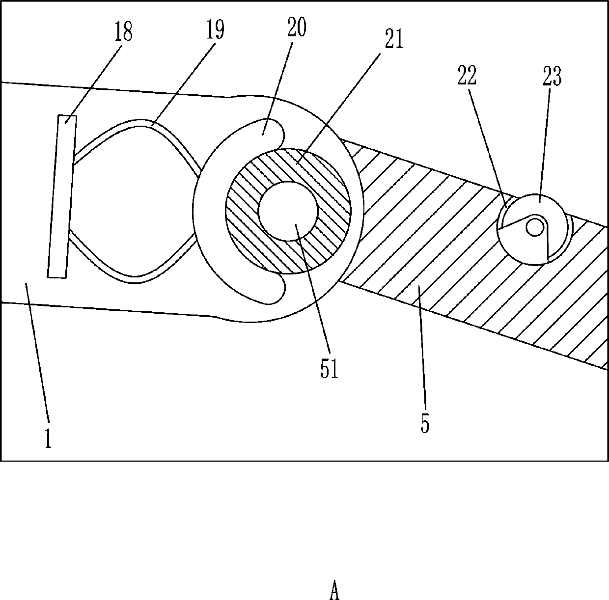
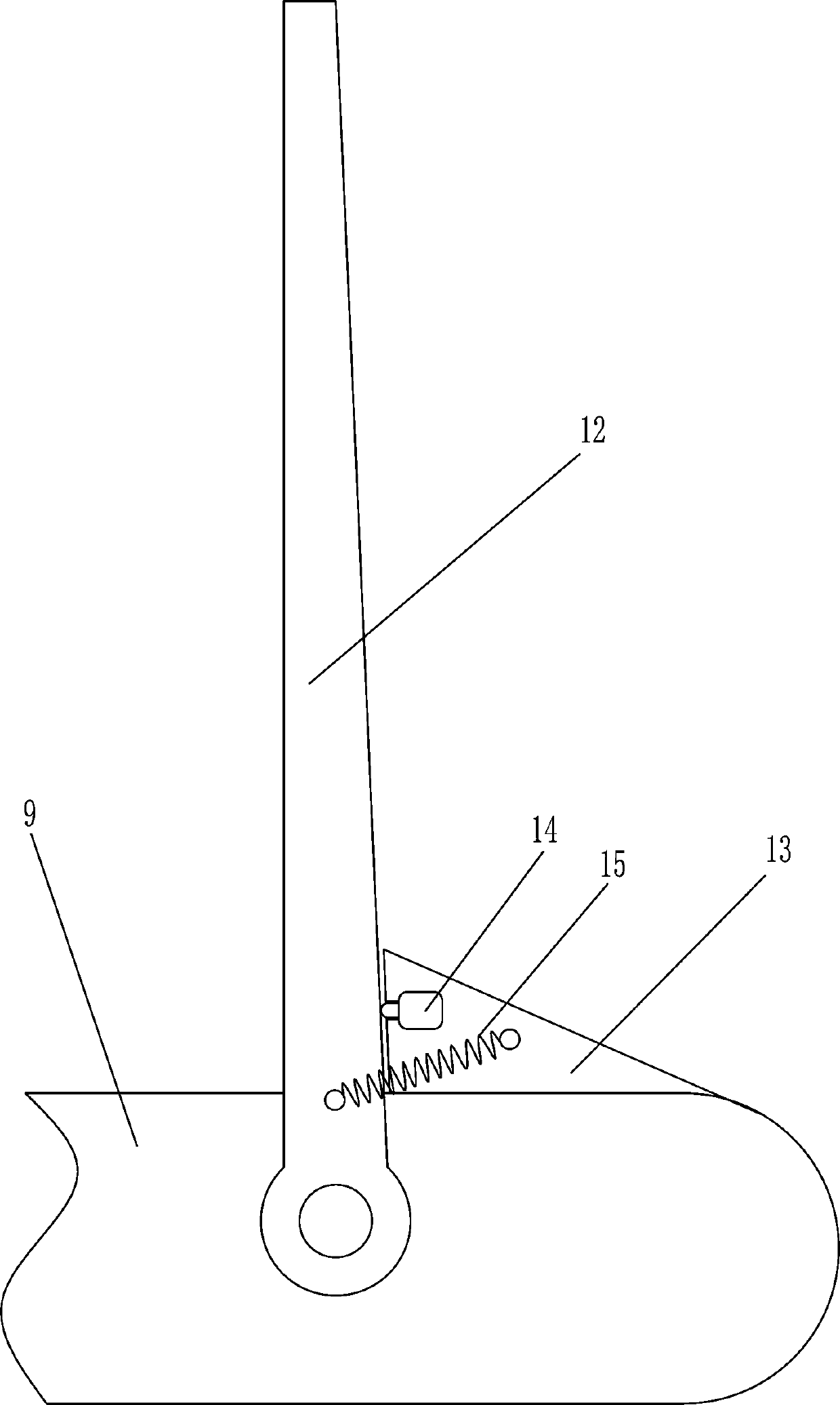
[0020] A cargo carton handling machine, such as Figure 1-8 As shown, it includes a load bearing plate 1, a one-way wheel 2, a universal wheel 3, a control box 4, a swash plate 5, a rotating shaft 51, a trolley frame 6, a protective rod 7, a connecting block 8, a first electric push rod 9, Second electric push rod 10, sliding shaft 101, waist frame 11, baffle plate 12, limit block 13, limit switch 14, first extension spring 15, infrared sensor 16, sponge cover 17, mounting plate 18, shrapnel 19 , friction plate 20, rubber cylinder 21, roller 23, up button 26 and down button 27, one-way wheels 2 are symmetrically connected to the left and right sides of the bottom of the load-bearing plate 1, and universal wheels 3 are connected to the middle of the bottom of the load-bearing plate 1 And the control box 4, the control box 4 is located on the left side of the universal wheel 3, the right part of the bearing plate 1 is rotatably connected with a rotating shaft 51, and the rotatin...
Embodiment 2
[0022] A cargo carton handling machine, such as Figure 1-8 As shown, it includes a load bearing plate 1, a one-way wheel 2, a universal wheel 3, a control box 4, a swash plate 5, a rotating shaft 51, a trolley frame 6, a protective rod 7, a connecting block 8, a first electric push rod 9, Second electric push rod 10, sliding shaft 101, waist frame 11, baffle plate 12, limit block 13, limit switch 14, first extension spring 15, infrared sensor 16, sponge cover 17, mounting plate 18, shrapnel 19 , friction plate 20, rubber cylinder 21, roller 23, up button 26 and down button 27, one-way wheels 2 are symmetrically connected to the left and right sides of the bottom of the load-bearing plate 1, and universal wheels 3 are connected to the middle of the bottom of the load-bearing plate 1 And the control box 4, the control box 4 is located on the left side of the universal wheel 3, the right part of the bearing plate 1 is rotatably connected with a rotating shaft 51, and the rotatin...
Embodiment 3
[0025] A cargo carton handling machine, such as Figure 1-8 As shown, it includes a load bearing plate 1, a one-way wheel 2, a universal wheel 3, a control box 4, a swash plate 5, a rotating shaft 51, a trolley frame 6, a protective rod 7, a connecting block 8, a first electric push rod 9, Second electric push rod 10, sliding shaft 101, waist frame 11, baffle plate 12, limit block 13, limit switch 14, first extension spring 15, infrared sensor 16, sponge cover 17, mounting plate 18, shrapnel 19 , friction plate 20, rubber cylinder 21, roller 23, up button 26 and down button 27, one-way wheels 2 are symmetrically connected to the left and right sides of the bottom of the load-bearing plate 1, and universal wheels 3 are connected to the middle of the bottom of the load-bearing plate 1 And the control box 4, the control box 4 is located on the left side of the universal wheel 3, the right part of the bearing plate 1 is rotatably connected with a rotating shaft 51, and the rotatin...
PUM
 Abstract
Description
Claims
Application Information
 - R&D
- Intellectual Property
- Life Sciences
- Materials
- Tech Scout
- Unparalleled Data Quality
- Higher Quality Content
- 60% Fewer Hallucinations
Browse by: Latest US Patents, China's latest patents, Technical Efficacy Thesaurus, Application Domain, Technology Topic, Popular Technical Reports.
© 2025 PatSnap. All rights reserved.Legal|Privacy policy|Modern Slavery Act Transparency Statement|Sitemap|About US| Contact US: help@patsnap.com