
New anti-failure damper and its installation method

A damper and anti-failure technology, which is applied in the direction of transportation and packaging, forced railway car stoppers, railway car body parts, etc., can solve the problems of friction disc damper clamping force reduction, damper failure, rail deformation and wear, etc. Achieve the effects of reducing the number of dampers arranged, improving the safety protection level, and reducing the distance occupied by lines

Active Publication Date: 2021-07-13
DALIAN JIAOTONG UNIVERSITY
View PDF5 Cites 0 Cited by
  • Summary
  • Abstract
  • Description
  • Claims
  • Application Information

AI Technical Summary

Problems solved by technology

However, after sliding for a certain distance, due to the wear and elastic deformation of the friction plate, the loosening of the bolts, and the failure of the bolts under stress for a long time, and even the deformation and wear of the rail, the positive pressure of the friction plate and the clamping force of the damper will appear. Lower or disappear, causing the damper to lose its effect
[0004] Most existing damper equipment is bulky and easy to install

Method used


Image

  • New anti-failure damper and its installation method
  • New anti-failure damper and its installation method
  • New anti-failure damper and its installation method

Examples


Embodiment 1

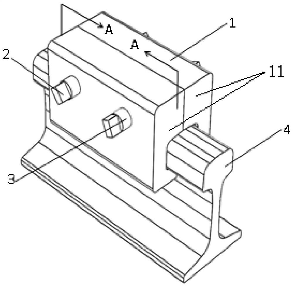
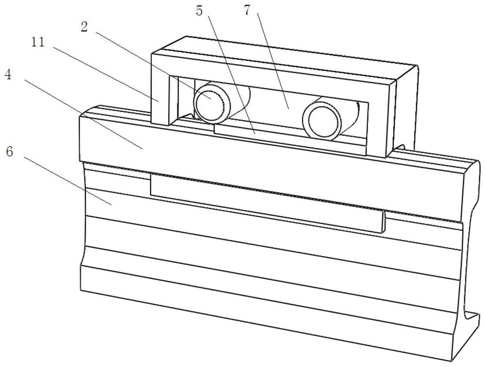
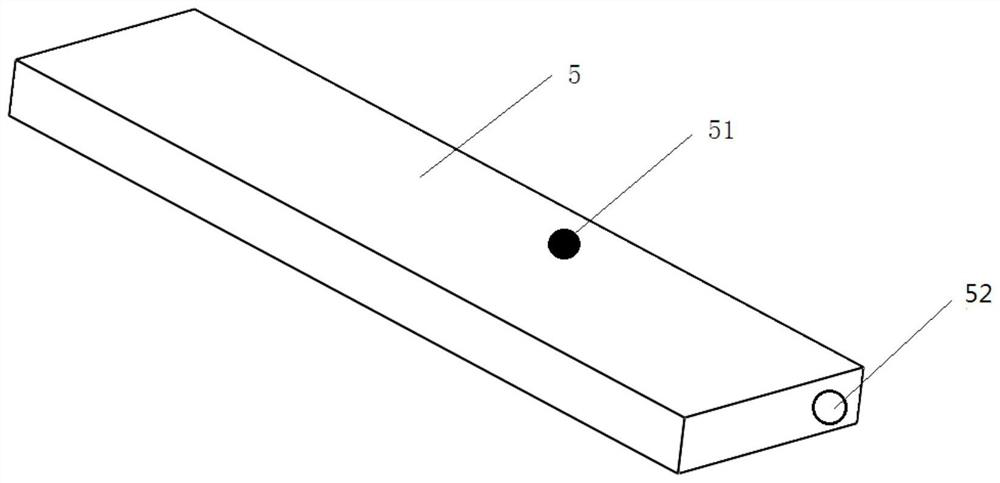
[0064] As shown in the figure, the present invention provides a new type of anti-failure damper. The friction plate 5, two half boxes 11 and eccentric body bolts 2 are assembled on the rail according to the instructions of the installation marks 52 to ensure the damping on the box 1. Arrow 111 in the sliding direction of the damper is the sliding direction of the damper.

[0065] After docking the two half-boxes 11, lock the eccentric body bolt 2 to prevent it from deflecting, and start pre-tightening the nut 3;

[0066] Use a torque wrench to apply torque to the eccentric body bolt 2, so that the eccentric body 21 presses the friction plate, and further locks the nut 3;

[0067] When the damper is pushed by the sliding car stopper or the front damper, one end of the box body 1 of the hit damper starts to be stressed and starts to move, and as a friction body, after receiving the force of the rail surface, it will After sliding, the eccentric body bolt 2 is driven to rotate, ...


PUM


Abstract

The invention relates to the technical field of safety protection at the end of rail transit trains or train lines, in particular to a damper structure for safety protection of large marshalling trains and high-speed trains. The box body of the present invention is composed of two semi-boxes with symmetrical structures: after the two half-boxes are merged, the upper part forms a complete cavity with an open bottom, and the lower part forms an installation tank with the same cross-sectional shape as the rail head and the rail waist; There is at least one horizontal screw hole on the side wall of the installation cavity of the half box; the eccentric body bolt is installed on the screw hole, and there is a long eccentric body bolt in the middle, and the fixed threads on both ends of the bolt are positive and negative. Threaded structure; nuts are installed on the fixed threads at both ends of the eccentric body bolts for installation and clamping of the box; the friction plate is a long strip structure, installed inside the installation cavity, between the rail head and the eccentric body bolts Between. The technical solution of the present invention solves the problems in the prior art: 1. After sliding for a certain distance, the damper fails; 2. The number of dampers is too large, which increases the budget; 3. The equipment is heavy and inconvenient to install.

Description

technical field [0001] The invention relates to the technical field of safety protection at the end of rail transit trains or train lines, in particular to a damper structure for safety protection of large marshalling trains and high-speed trains. Background technique [0002] The stop device at the end of the track line is generally equipped with a damper to consume the impact kinetic energy of the train. With the improvement of the safety protection level, it is often necessary to realize parking within a short distance, and it is necessary to increase the number of dampers to meet the parking requirements. It is necessary to increase the reserved length and increase the budget when designing the line. The number of damper arrangements is limited by the reserved length of existing lines. [0003] Most existing dampers are designed to clamp the rail on both sides of the transverse bolts, and the upper end is vertically pressed by the bolt to the friction plate at the upper...

Claims


Application Information

Patent Timeline
Patent Type & Authority Patents(China)
IPC IPC(8): B61K7/18
CPCB61K7/18
Inventor 刘爽薛齐文赵旭宝
Owner DALIAN JIAOTONG UNIVERSITY
Learn More