Multifunctional fan

A multi-functional, fan technology, applied in space heating and ventilation, space heating and ventilation control input, heating method, etc., can solve the problems of low degree of intelligence, unsuitable for portability, and bulky, and achieve the degree of intelligence High, easy to promote, small size effect

Inactive Publication Date: 2019-12-06
TIANHE COLLEGE GUANGDONG POLYTECHNIC NORMAL UNIV
View PDF3 Cites 1 Cited by
  • Summary
  • Abstract
  • Description
  • Claims
  • Application Information

AI Technical Summary

Problems solved by technology

[0004] To sum up, after massive searches by the applicant, this field at least has the disadvantages of bulky, unsuitable for portability, single function and low degree of intelligence
Therefore, the existing fan can no longer meet people's needs

Method used


Image

  • Multifunctional fan
  • Multifunctional fan
  • Multifunctional fan

Examples


Embodiment 1

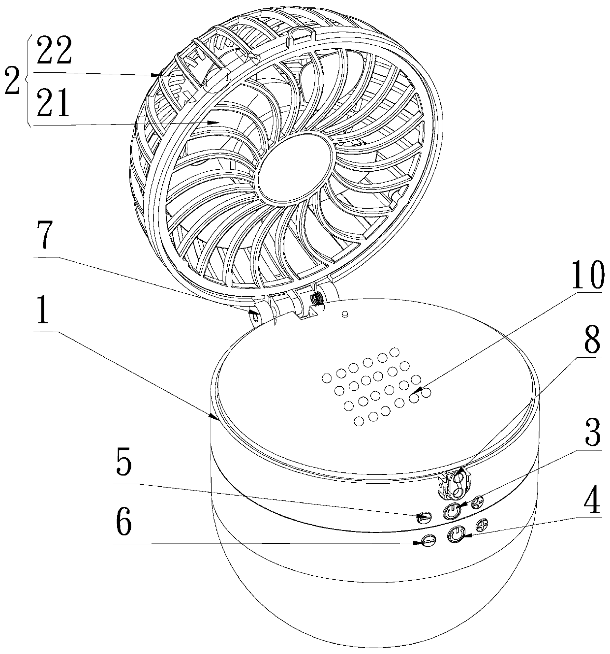
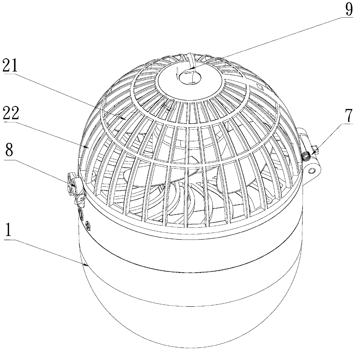
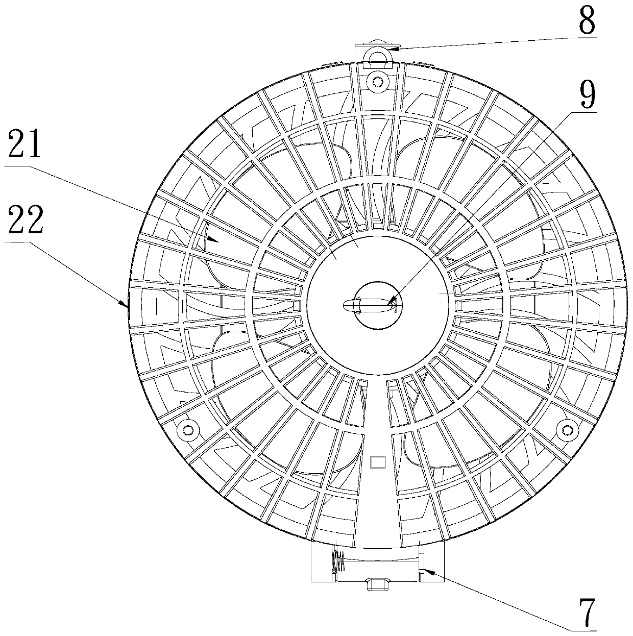
[0029] Such as Figure 1~2 The multifunctional fan shown includes a housing 1 and an air supply device 2; the air supply device 2 is turned over and connected with the housing 1 and forms a turning path; the turning path includes the blowing device 2 Turn over the folded section on the housing and the use section of the air supply device 2 to open on the housing 1; the housing 1 is provided with a cavity; the cavity is provided with There is a humidifying device; the casing 1 is provided with an air outlet 10 communicating with the output end of the humidifying device; the humidifying device includes a water storage chamber; An electric control system for water quantity; the electric control system includes a processor, a humidity sensor for sensing air humidity, and a valve body assembly arranged at the outlet of the water storage chamber; the valve body assembly and the humidity sensor respectively connected to the processor; the wind direction of the air supply device 2 is...

Embodiment 2

[0039] Such as Figure 1~2 The multifunctional fan shown includes a housing 1 and an air supply device 2; the air supply device 2 is turned over and connected with the housing 1 and forms a turning path; the turning path includes the blowing device 2 Turn over the folded section on the housing and the use section of the air supply device 2 to open on the housing 1; the housing 1 is provided with a cavity; the cavity is provided with There is a humidifying device; the casing 1 is provided with an air outlet 10 communicating with the output end of the humidifying device; the humidifying device includes a water storage chamber; An electric control system for water quantity; the electric control system includes a processor, a humidity sensor for sensing air humidity, and a valve body assembly arranged at the outlet of the water storage chamber; the valve body assembly and the humidity sensor respectively connected to the processor; the wind direction of the air supply device 2 is...


PUM


Abstract

The invention discloses a multifunctional fan. The multifunctional fan is characterized by comprising a shell and an air supply device; the air supply device is connected with the shell in an overturning mode and an overturning path is formed; the overturning path comprises a folding section for overturning and folding the air supply device on the shell and a using section for overturning and unfolding the air supply device on the shell; a cavity is arranged in the shell; a humidifying device is arranged in the cavity; the shell is provided with an air outlet communicating with an output end of the humidifying device; the humidifying device comprises a water storage cavity; the cavity is further internally provided with an electric control system for controlling output water quantity of the water storage cavity; the electric control system comprises a processor, a humidity sensor for sensing air humidity, and a valve body component arranged at an output port of the water storage cavity; the valve body component and the humidity sensor are connected with the processor; and the airflow direction of the air supply device intersects with the water mist flow direction of the humidifyingdevice. The multifunctional fan has the advantages of small size, convenient carrying, multiple functions and high intelligence degree.

Description

technical field [0001] The invention relates to the technical field of small household electrical appliances, in particular to a multifunctional fan. Background technique [0002] In the existing small household appliances, the electric fan generally only has the function of blowing air, and does not have the function of a humidifier. On the contrary, the humidifier only has the function of humidifying the air, but does not have the function of blowing air. When the weather is hot, we cannot do without the fan, and after the fan works for a period of time, the circuit board will heat up, and the weather is hot, resulting in relatively dry and hot air. At this time, the wind blown by the fan is hot, which cannot be better. To achieve the effect of heat dissipation and cooling, it will even feel hotter and hotter; moreover, the air in summer is generally relatively dry, so a humidifier is needed to add moisture to the air to make users feel comfortable. Now there is a combina...

Claims


Application Information

Patent Timeline
IPC IPC(8): F04D25/08F04D29/52F04D29/00F04D27/00F04D29/70F24F6/12F24F11/89F24F110/20
CPCF04D25/08F04D27/00F04D29/002F04D29/522F04D29/703F24F6/12F24F11/89F24F2110/20
Inventor 黄育文
Owner TIANHE COLLEGE GUANGDONG POLYTECHNIC NORMAL UNIV
Why Eureka
Try Eureka