High-precision high-speed glass rotary disc visual inspection machine

A visual inspection, high-precision technology, applied in the field of visual inspection, can solve the problems of high-speed inspection of the inspection machine, no open and efficient operation method, etc., to achieve the effect of reducing follow-up processes, optimizing working procedures, and improving inspection efficiency

Inactive Publication Date: 2019-12-06
广东西尼科技有限公司
View PDF7 Cites 10 Cited by
  • Summary
  • Abstract
  • Description
  • Claims
  • Application Information

AI Technical Summary

Problems solved by technology

[0003] Our company disclosed the hardware structure and basic usage method in this technical solution, but did not disclose the method to make it operate efficiently. The existing technology cannot obtain the effect of high-speed detection through this detection machine

Method used


Image

  • High-precision high-speed glass rotary disc visual inspection machine

Examples


Embodiment 1

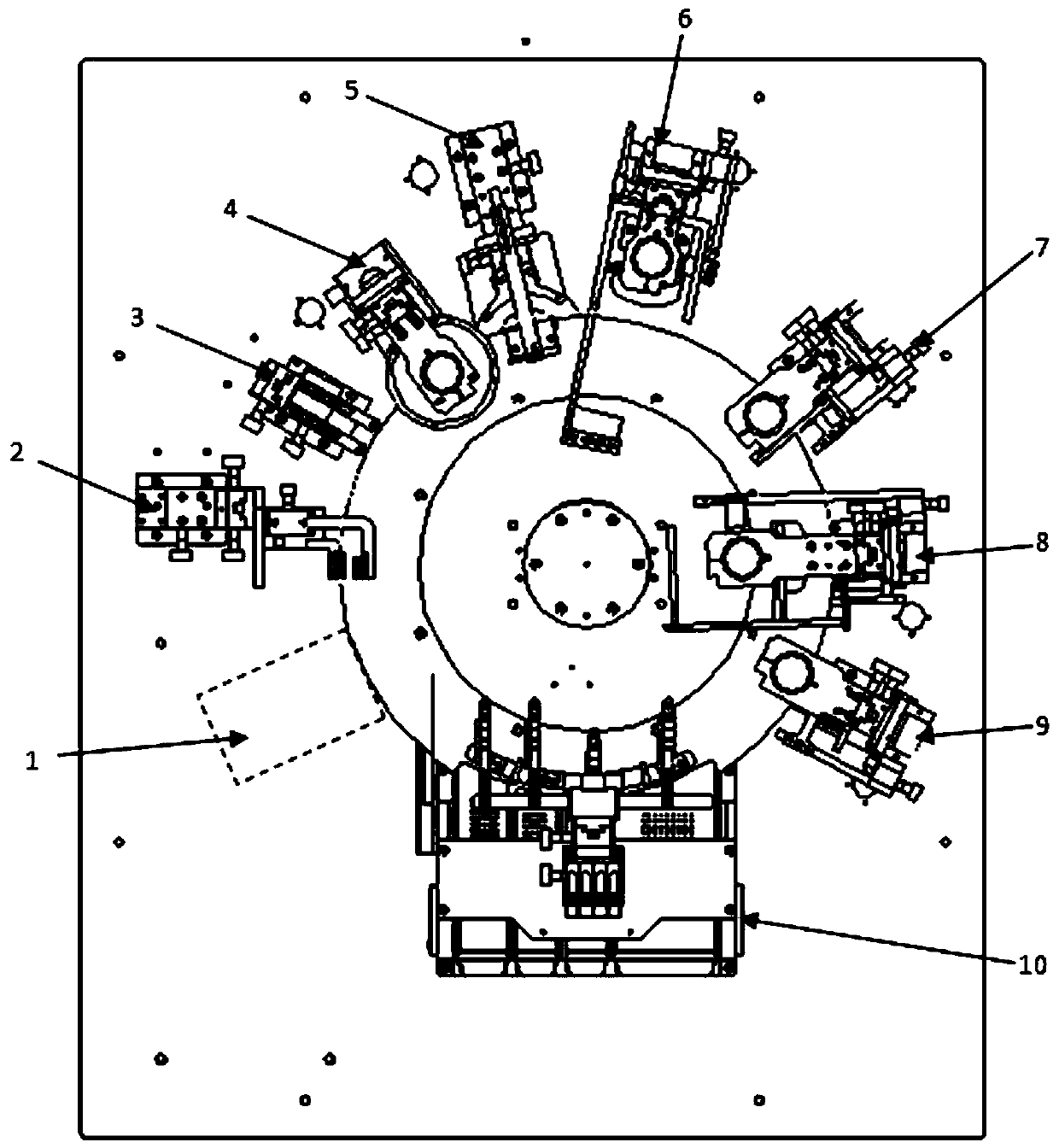
[0018] Such as figure 1 As shown, a high-precision and high-speed glass turntable visual inspection machine includes a cabinet and a detection device installed in the cabinet. Visual detection camera and unloading mechanism, the center of the bottom plate is installed with a rotating glass plate through a rotating shaft, and the rotating shaft is connected to a motor through a transmission mechanism. The feeding mechanism, the sensor, the first visual detection camera, the second visual detection camera, the third visual detection camera, the fourth visual detection camera, the fifth visual detection camera, the sixth visual detection camera and the unloading mechanism, wherein the fifth visual detection camera The lens of the detection camera extends into the bottom surface of the rotating glass disk and the lens is vertically facing upwards. One side of the fifth visual inspection camera is equipped with a reflector through an adjustment bracket, and the reflector is located...

Embodiment 2

[0025] A high-precision and high-speed glass turntable visual inspection machine, which includes a cabinet and a detection device installed in the cabinet, is characterized in that: the detection device includes a bottom plate, a rotating glass disk, an array feeding mechanism, a sensor, and multiple visual detection cameras As well as the unloading mechanism, the center of the bottom plate is equipped with a rotating glass plate through a rotating shaft, and the rotating shaft is connected to a motor through a transmission mechanism. The bottom plate is located on the outer periphery of the rotating glass plate and is surrounded by an entire row of feeding mechanisms in a clockwise direction. , sensor, the first visual detection camera, the second visual detection camera, the third visual detection camera, the fourth visual detection camera, the fifth visual detection camera, the sixth visual detection camera and the blanking mechanism, wherein the fifth visual detection camera...


PUM


Abstract

The invention relates to the technical field of visual inspection, in particular to a high-precision high-speed glass rotary disc visual inspection machine. An industrial personal computer is installed in a machine cabinet, and a sensor, first to sixth visual inspection cameras and a discharging mechanism are all in signal connection with the industrial personal computer; and an arraying and feeding mechanism automatically arrays materials and evenly feeds the materials, a rotary disc rotates at the uniform speed, the sensor is triggered when each material passes through the sensor, the sensortransmits signals to the industrial personal computer, the industrial personal computer starts to calculate time nodes when the materials pass through all inspection cameras and time nodes when the materials reach the discharging mechanism and issues instructions to make all inspection cameras to shoot the materials at the corresponding time nodes, each inspection camera feeds back image data tothe industrial personal computer after shooting, the industrial personal computer counts the material states, the materials are blown into corresponding material boxes when reaching the discharging device according to the different states, and the efficiency is improved.

Description

technical field [0001] The invention relates to the technical field of visual inspection, in particular to a high-precision and high-speed glass turntable visual inspection machine. Background technique [0002] A visual inspection machine or a visual inspection robot is a device that visually inspects parts produced by a factory through a visual camera. The detection device in the cabinet is characterized in that: the detection device includes a base plate, a rotating glass disc, an array loading mechanism, a sensor, a plurality of visual detection cameras and a feeding mechanism, and a rotating glass disc is installed in the center of the base plate through a rotating shaft. The motor is connected through the transmission mechanism, and the bottom plate is located on the outer periphery of the rotating glass disk. Around the rotating glass disk, a whole column of feeding mechanism, sensors, first visual detection camera, second visual detection camera, and second visual de...

Claims


Application Information

Patent Timeline
Patent Type & Authority Applications(China)
IPC IPC(8): B07C5/02B07C5/34B07C5/38
CPCB07C5/02B07C5/34B07C5/365B07C5/38
Inventor 谢华辉朱金伟
Owner 广东西尼科技有限公司
Why Eureka
Try Eureka