Robust adaptive beamforming method based on spatial smoothing

An adaptive beam, spatial smoothing technology, applied in the direction of spatial transmit diversity, diversity/multi-antenna systems, electrical components, etc., can solve the problems of beamformer performance degradation, expected signal cancellation, covariance matrix rank loss, etc. Optimum performance, the effect of reducing coherence

Pending Publication Date: 2019-12-03
HARBIN INST OF TECH
View PDF6 Cites 3 Cited by
  • Summary
  • Abstract
  • Description
  • Claims
  • Application Information

AI Technical Summary

Problems solved by technology

[0004] The purpose of the present invention is to overcome the coherence of the desired signal and the interference signal. The covariance matrix of the array received signal will have a rank deficit phenomenon. Using the traditional adaptive beamforming algorithm will lead to the cancellation of the desired signal, thereby causing a sharp drop in the performance of the beamformer. drop problem, providing a robust adaptive beamforming method based on spatial smoothing

Method used


Image

  • Robust adaptive beamforming method based on spatial smoothing
  • Robust adaptive beamforming method based on spatial smoothing
  • Robust adaptive beamforming method based on spatial smoothing

Examples


specific Embodiment approach 1

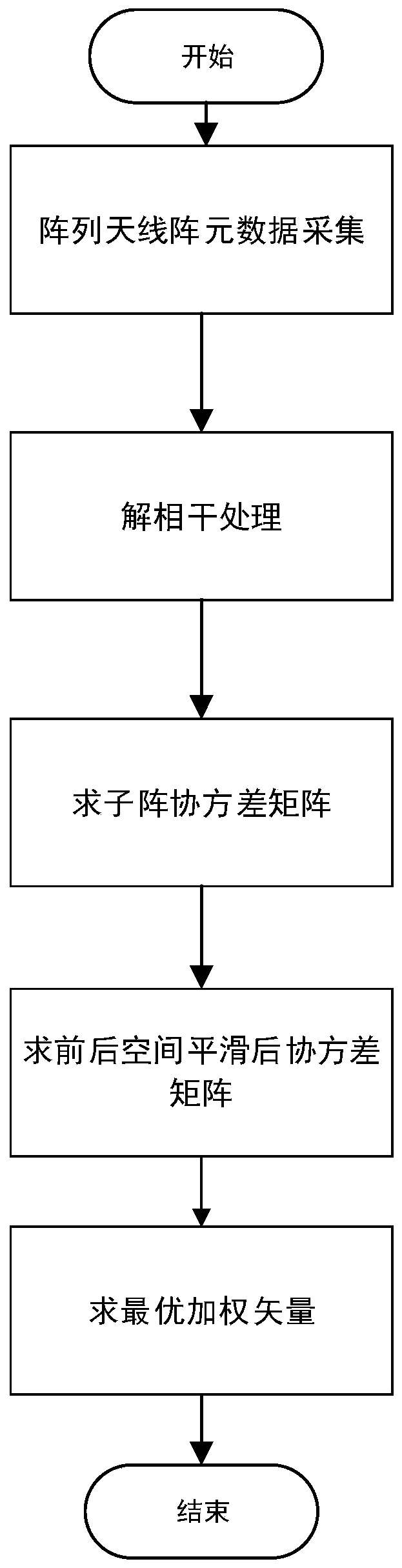
[0040] Specific implementation mode one: a robust adaptive beamforming method based on spatial smoothing, characterized in that the implementation process of the method is:

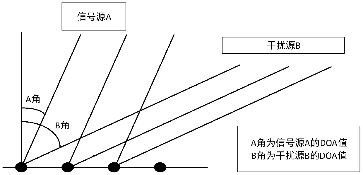
[0041] Step 1. Data collection: collect the array antenna element signal, which contains the target signal (expected signal) s in the signal x(n) 0 (n), coherent interference signal s k (n) and uncorrelated interfering signal s P (n),

[0042]

[0043] Among them, a(θ k ) and a(θ p ) are respectively the complex envelope of the kth coherent interference signal and the pth uncorrelated interference signal;

[0044] n in brackets is the snapshot number of the signal, a(θ 0 ) is the steering vector of the array element signal, n(n) represents noise, and n outside the brackets represents noise;

[0045] Step 2, decoherence processing:

[0046] At present, the array covariance matrix is ​​used to perform decoherence processing,

[0047]

[0048] A c and A u is an array flow matrix.

[0049]Sin...

specific Embodiment approach 2

[0063] Embodiment 2: After step 4 is executed, if the data of the sub-arrays are arranged from the back to the front, this is the backward spatial smoothing algorithm, and the combination of the two is the forward and backward spatial smoothing algorithm. After smoothing, the data covariance matrix will be restored to full rank, so the weight vector can be obtained, and then processed by Capon beamforming algorithm. Others are the same as step 1.

specific Embodiment approach 3

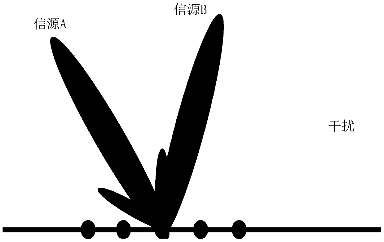
[0064] Specific implementation mode three: in step five, the process of seeking the optimal weight vector:

[0065] The adaptive beamforming constraints are expressed as:

[0066]

[0067] The optimal weight vector for beamforming obtained by the forward spatial smoothing algorithm:

[0068] Others are the same as step 1 or 2.


PUM


Abstract

The invention discloses a robust adaptive beamforming method based on spatial smoothing. The invention relates to the field of array antenna self-adaptive beam forming, and aims to solve the problemsthat expected signals are coherent with interference signals, a covariance matrix of array receiving signals can generate a rank loss phenomenon, the expected signals can be cancelled by using a traditional self-adaptive beam forming algorithm, and the performance of a beam forming device is sharply reduced. On the basis of the worst performance optimal criterion, interference and noise power output by the array are minimized on the basis of ensuring that all possible expected signal steering vectors and sampling correlation matrixes pass through a beam former without attenuation. According tothe invention, the phenomenon that the covariance matrix of the array receiving signal has rank loss due to coherence of the expected signal and the interference signal is overcome, and the performance of the beamformer is improved.

Description

technical field [0001] The invention relates to the field of array antenna adaptive beamforming, in particular to a robust adaptive beamforming method based on spatial smoothing. Background technique [0002] In the actual environment, due to the existence of obstacles such as mountains, tall buildings, and clouds, as well as some man-made (intelligent interference) and non-man-made (electronic signal interference between instruments and equipment) factors, the desired signal and the interference signal are coherent, and the array received signal The covariance matrix will have a rank deficit, which will cause the eigenvectors of the signal subspace to be lost. Using the traditional adaptive beamforming algorithm will lead to the cancellation of the desired signal, resulting in a sharp decline in the performance of the beamformer. In order to solve the problem of signal source coherence, it is necessary to decoherently process the received data. The beamforming algorithms in...

Claims


Application Information

Patent Timeline
IPC IPC(8): H04B7/08
CPCH04B7/086
Inventor 吴芝路宋晓凯尹振东吴明阳李波
Owner HARBIN INST OF TECH
Why Eureka
Try Eureka