A single-drive umbrella antenna with primary and secondary surfaces deployed synchronously

An umbrella antenna, single-drive technology, applied in the field of satellite antennas, can solve the problems of complex drive mechanism, poor synchronization during deployment, and not compact structure, and achieve the effects of good synchronization, compact structure, and reduced impact

Active Publication Date: 2020-11-03
XIDIAN UNIV
View PDF4 Cites 0 Cited by
  • Summary
  • Abstract
  • Description
  • Claims
  • Application Information

AI Technical Summary

Problems solved by technology

[0006] The purpose of the present invention is to overcome the deficiencies of the above-mentioned prior art, and propose a single-drive umbrella-shaped antenna for synchronous deployment of the main and secondary surfaces, so as to improve the efficiency of the parabolic antenna, solve the problems of complex drive mechanism, poor synchronization of the deployment process, and insufficient compact structure

Method used


Image

  • A single-drive umbrella antenna with primary and secondary surfaces deployed synchronously
  • A single-drive umbrella antenna with primary and secondary surfaces deployed synchronously
  • A single-drive umbrella antenna with primary and secondary surfaces deployed synchronously

Examples


Embodiment Construction

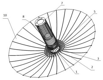
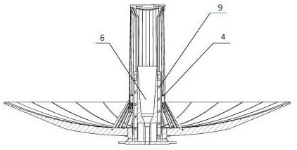
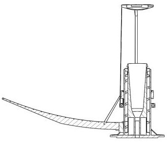
[0040] refer to Figure 1 to Figure 3 , figure 1 It is a schematic diagram of the overall structure of the present invention in expanded state; figure 2 It is a schematic diagram of the unfolded section of the overall structure of the present invention; image 3 It is a schematic diagram of the unfolded section of a single antenna rib of the present invention; the present invention includes a base hub 1, an antenna rib 2, a sleeve 3, a slider ring 4, a connecting rod 5, a feed horn 6, a secondary reflector 7, a rope 8, and a spring 9 , silk screen reflective surface 10, the base hub 1 is a fixed component, which is the basis of the entire antenna connection; the antenna rib 2 is hinged with the base hub 1, and its root can rotate around the hinge; the sleeve 3 It is fixedly installed on the upper part of the base hub 1 coaxially with the base hub 1, wherein a fixed pulley is uniformly fixed in the lower part in the circumferential direction; the slider ring 4 is connected w...


PUM


Abstract

The invention discloses a single-drive umbrella-shaped antenna with a main surface and an auxiliary surface synchronously unfolded. The single-drive umbrella-shaped antenna is composed of a base hub,an antenna rib, a sleeve, a sliding block ring, a connecting rod, a feed source horn, an auxiliary reflecting surface, a rope, a spring and a wire mesh reflecting surface. The antenna rib is hinged with the base hub, the sleeve, the feed source horn and the base hub are coaxially and fixedly connected, the sliding block ring and the auxiliary reflecting surface respectively sleeve on the sleeve and the feed source horn, two ends of the connecting rod are respectively hinged with the sliding block ring and the antenna rib, two ends of the rope are respectively connected with the auxiliary reflecting surface and the sliding block ring, and the spring is used for driving the auxiliary reflecting surface. During folding, the spring is compressed in the sleeve by the auxiliary reflecting surface. When the antenna is unfolded, the spring drives the auxiliary reflecting surface to ascend, the sliding block ring is pulled to translate downwards under the action of the rope and a fixed pulley,and the antenna rib is driven by the connecting rod to unfold synchronously. Synchronous unfolding of the main and auxiliary surfaces of the antenna is achieved through single driving, and the umbrella-shaped deployable antenna has the advantages of the good unfolding synchronism, the small folding size and the simple structure, and can be applied to design of high-precision umbrella-shaped deployable antennas.

Description

technical field [0001] The invention belongs to the technical field of satellite antennas, in particular to a single-drive umbrella-shaped antenna with synchronous deployment of the main and secondary surfaces in the field of satellite antennas, which can be applied to the design of high-precision umbrella-shaped deployable antennas. Background technique [0002] The space-borne deployable antenna is an important part of the satellite structure, and the rapid development of aerospace technology puts forward higher and higher requirements for it. At present, the more mature spaceborne deployable antennas, such as fixed surface, inflatable, frame and surrounding truss and other deployable reflector antennas, are difficult to meet the requirements of large aperture, high storage ratio and high precision at the same time. The umbrella-shaped deployable antenna has outstanding advantages in terms of storage ratio, surface density, deployment performance, and shape and surface mai...

Claims


Application Information

Patent Timeline
Patent Type & Authority Patents(China)
IPC IPC(8): H01Q19/19H01Q15/16H01Q1/08H01Q13/02
CPCH01Q1/084H01Q13/02H01Q15/161H01Q19/19
Inventor 张树新韩晓童邢永涛
Owner XIDIAN UNIV
Why Eureka
Try Eureka