Manufacturing method of transformer coil

A technology of transformer coils and manufacturing methods, applied in the direction of inductance/transformer/magnet manufacturing, electrical components, circuits, etc., can solve the problem of winding different coil turns, and achieve the effect of improving multifunctionality

Active Publication Date: 2019-12-03
湖南利航电子有限公司
View PDF4 Cites 2 Cited by
  • Summary
  • Abstract
  • Description
  • Claims
  • Application Information

AI Technical Summary

Problems solved by technology

[0007] In view of the problems in the prior art, the purpose of the present invention is to provide a transformer coil manufacturing method to solve the existing disclosed coil manufacturing method, which can only produce a fixed number of coil turns, and it is difficult to wind different coils through this device The technical problem of the number of turns

Method used


Image

  • Manufacturing method of transformer coil
  • Manufacturing method of transformer coil
  • Manufacturing method of transformer coil

Examples


Embodiment 1

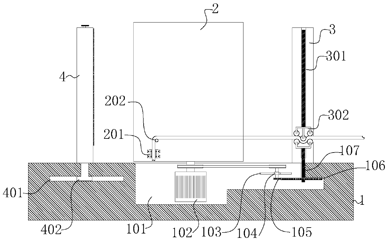
[0047] see Figure 1-8 , is a schematic diagram of the overall structure of a method for manufacturing a transformer coil. A strip-shaped flat conductor is helically wound to form a helical structure, which includes the following steps:

[0048]S1), material preparation, preparing a flat conductor, and covering the surface of the flat conductor with paint to insulate the contact between two adjacent flat conductors;

[0049] S2), spiral winding, fixing one end of the flat conductor prepared in step S1 to the bottom of the inner mandrel; rotating the inner mandrel so that the flat conductor is wound around the inner mandrel to form a helical structure;

[0050] S3), tightness adjustment, when winding the flat conductor in step S2 on the inner mandrel, tighten the wound flat conductor to make the formed spiral structure more compact;

[0051] S4), the structure is shaped, and the flat conductor being wound in step S2 is compressed and shaped, so that the surface texture of the ...

Embodiment 2

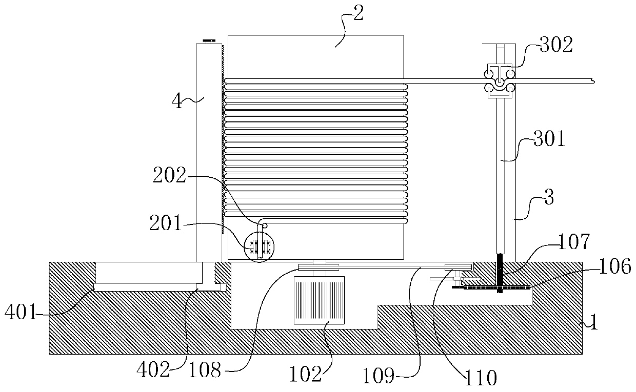
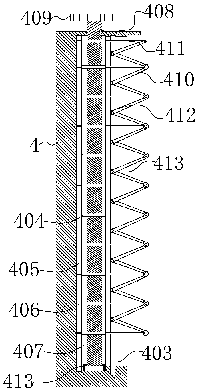
[0064] see Figure 1-8 , is a schematic diagram of the overall structure of another transformer coil manufacturing method. This embodiment has similarities with Embodiment 1, and the similarities will not be described in this embodiment. The specific differences are:

[0065] A third sliding seat 402 is fixed on the bottom of the sidewall 4 , and the third sliding seat 402 is embedded in a third sliding groove 401 , and the third sliding groove 401 is arranged on the top of the chassis base 1 . The rib 4 is set to a square column structure, the top of the rib 4 is provided with a circular hole 407, and the bottom of the circular hole 407 is provided with a fixed seat 413; the side wall of the rib 4 is provided with a square hole 413, and the square hole 413 is connected with the circular hole 407 communicates, the hole wall of square hole 413 is symmetrically provided with the fourth chute 403, the side wall of circular hole 407 is provided with the 5th chute 405; Threaded rod...


PUM


Abstract

The invention discloses a manufacturing method of a transformer coil, and relates to the technical field of electrical equipment. The manufacturing method comprises the following steps: S1, material preparation: preparing a flat conductor, coating the surface of the flat conductor with paint and insulating two adjacent flat conductors when in contact; S2, spiral winding: fixing one end of the flatconductor prepared in the step S1 to the bottom end of an inner core mold; and winding the flat conductor around the inner core mold to form a spiral structure through rotation of the inner core mold; and S3, tightness adjustment: tightening the wound flat conductor to make the formed spiral structure more compact when the flat conductor in the step S2 is wound on the inner core mold,. Accordingto the manufacturing method, the changeover gears with different diameters are changed and changed rotating gears are normally meshed with the second gear so that the distance between the two adjacentturns of each produced coil is identical after the coil turns of the device are changed.

Description

technical field [0001] The invention relates to the technical field of electrical equipment, in particular to a method for manufacturing a transformer coil. Background technique [0002] The transformer is a device that uses the principle of electromagnetic induction to change the AC voltage. The main components are the primary coil, the secondary coil and the iron core (magnetic core). The winding connected to the power supply is called the primary coil, and the remaining windings are called the secondary coil. It can transform AC voltage, current and impedance. The simplest core transformer consists of a core made of soft magnetic material and two coils with unequal turns on the core. [0003] Existing patent No. CN201810971355.3 discloses a coil manufacturing method, which is characterized in that it crimps strip-shaped flat conductors to form a spiral structure, and the coil manufacturing method includes: preparing a plurality of flat conductors, the The plurality of f...

Claims


Application Information

Patent Timeline
IPC IPC(8): H01F41/061H01F41/094H01F41/077
CPCH01F41/061H01F41/077H01F41/094
Inventor 刘敏洁方坤棉
Owner 湖南利航电子有限公司
Why Eureka
Try Eureka