
Time-sharing drive circuit for auto-stereoscopic display optical fiber backlight source

A technology of stereoscopic display and driving circuit, which is applied in optics, optical components, static indicators, etc., can solve the problems of naked-eye 3D display resolution reduction, etc., and achieve anti-vertigo visual fatigue, strong environmental adaptability, and high signal acquisition accuracy Effect

Pending Publication Date: 2019-12-03
HUAQIAO UNIVERSITY
View PDF0 Cites 0 Cited by
  • Summary
  • Abstract
  • Description
  • Claims
  • Application Information

AI Technical Summary

Problems solved by technology

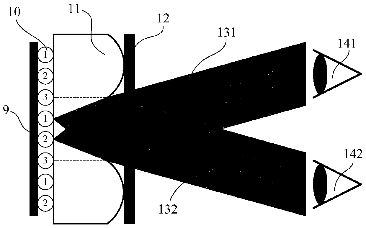
[0004] The purpose of the present invention is to overcome the deficiencies of the prior art, and propose a time-sharing drive circuit for an autostereoscopic display fiber optic backlight. By adopting sequential backlight control, the left and right parallax images played on the liquid crystal display screen are respectively projected to the left and right sides of the viewer. eye, realize naked-eye 3D display, and overcome the problem of resolution reduction of other kinds of naked-eye 3D displays

Method used


Image

  • Time-sharing drive circuit for auto-stereoscopic display optical fiber backlight source
  • Time-sharing drive circuit for auto-stereoscopic display optical fiber backlight source
  • Time-sharing drive circuit for auto-stereoscopic display optical fiber backlight source

Examples


Embodiment Construction

[0030] In order to make the objectives, technical solutions and advantages of the present invention clearer, the following will further describe the embodiments of the present invention in detail with reference to the accompanying drawings.

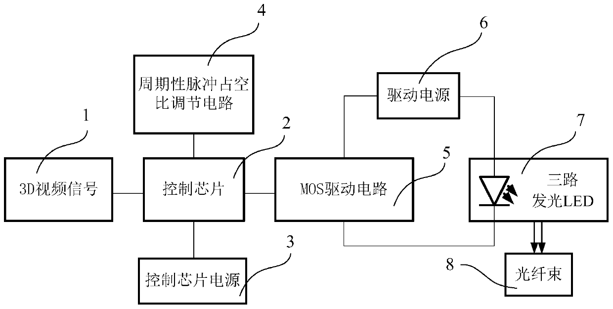
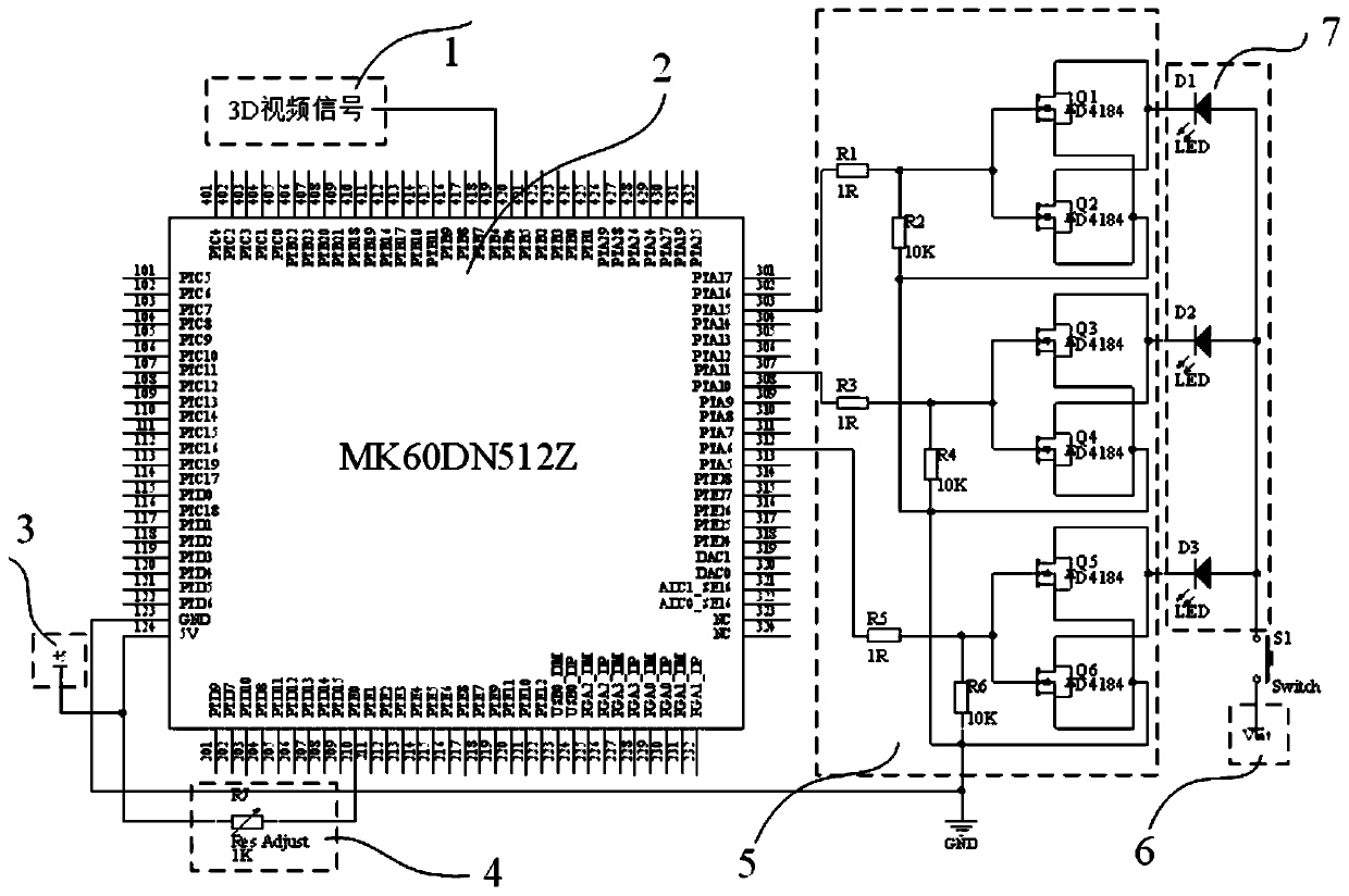
[0031] See Figure 1 to Figure 5 As shown, the autostereoscopic display optical fiber backlight time-sharing driving circuit of the present invention includes a 3D video signal 1, a control chip 2, a control chip power supply 3, a periodic pulse duty cycle adjustment circuit 4, a MOS driving circuit 5, and a driving power supply 6. , Power switch S1, three-way light-emitting LED7 and optical fiber bundle 8.

[0032] The autostereoscopic display optical fiber backlight source of the present invention adopts timing backlight control to project the left and right parallax images played on the liquid crystal image display screen to the left and right eyes of the viewer respectively to realize naked-eye 3D display. The divergent white light beam e...


PUM


Abstract

The invention discloses a time-sharing driving circuit for an auto-stereoscopic display optical fiber backlight source which comprises a 3D video signal, a control chip, a control chip power supply, aperiodic pulse duty ratio adjusting circuit, an MOS driving circuit, a driving power supply, three paths of light-emitting LEDs and an optical fiber bundle. The 3D video signal is connected with thecontrol chip to provide a pulse signal; the control chip power supply is connected with the control chip to provide power; the periodic pulse duty ratio adjusting circuit is connected with the controlchip so as to adjust the periodic pulse duty ratio output to the MOS drive circuit by the control chip. The control chip is connected with the MOS driving circuit to output a periodic pulse signal; the MOS driving circuit is connected with the three paths of light-emitting LEDs; and the three paths of LEDs are connected with the optical fiber bundle so as to guide light into the optical fibers. The left parallax image and the right parallax image played on the liquid crystal image display screen are projected to the left eye and the right eye of a viewer respectively, and naked eye 3D displayis achieved.

Description

Technical field [0001] The invention belongs to the field of optical fiber lighting and display, and in particular relates to a time-sharing driving circuit for an optical fiber backlight source for autostereoscopic display. Background technique [0002] With the rapid development of electronic technology, the penetration rate of liquid crystal displays is getting higher and higher. The backlight drive circuit is an important component of the liquid crystal display. Since the liquid crystal molecules themselves do not emit light, a backlight is required to provide a dedicated light source for the liquid crystal display, such as LCD TVs, LCD computers, etc. The backlight of the LCD display is mainly a light-emitting diode light bar, and it is a multi-channel light bar. Moreover, under the current trend of display switching functions of the display, most displays require the system to dynamically realize the smooth switching between 2D and 3D functions. The performance is that the...

Claims


Application Information

Patent Timeline
Patent Type & Authority Applications(China)
IPC IPC(8): G09G3/34G02B27/22
CPCG09G3/3406
Inventor 李梓润庄其仁林青何涌郜飞飞
Owner HUAQIAO UNIVERSITY
Learn More