mV signal measurement temperature compensation device

A technology of temperature compensation device and signal measurement, which is applied in the direction of measurement device, volume change compensation/correction device, measurement capacity, etc. It can solve the problems of difficult polynomial compensation coefficient setting, etc., and achieve shortened development cycle, small flow output delay, and high performance. The effect of low consumption

Pending Publication Date: 2019-12-03
CHONGQING CHUANYI AUTOMATION
View PDF0 Cites 1 Cited by
  • Summary
  • Abstract
  • Description
  • Claims
  • Application Information

AI Technical Summary

Problems solved by technology

However, since the secondary instrument is a pure analog circuit, it is difficult to realize the polynomial compensation coefficient setting

Method used


Image

  • mV signal measurement temperature compensation device
  • mV signal measurement temperature compensation device
  • mV signal measurement temperature compensation device

Examples


Embodiment Construction

[0029] The implementation of the present invention will be illustrated by specific specific examples below, and those skilled in the art can easily understand other advantages and effects of the present invention from the contents disclosed in this specification.

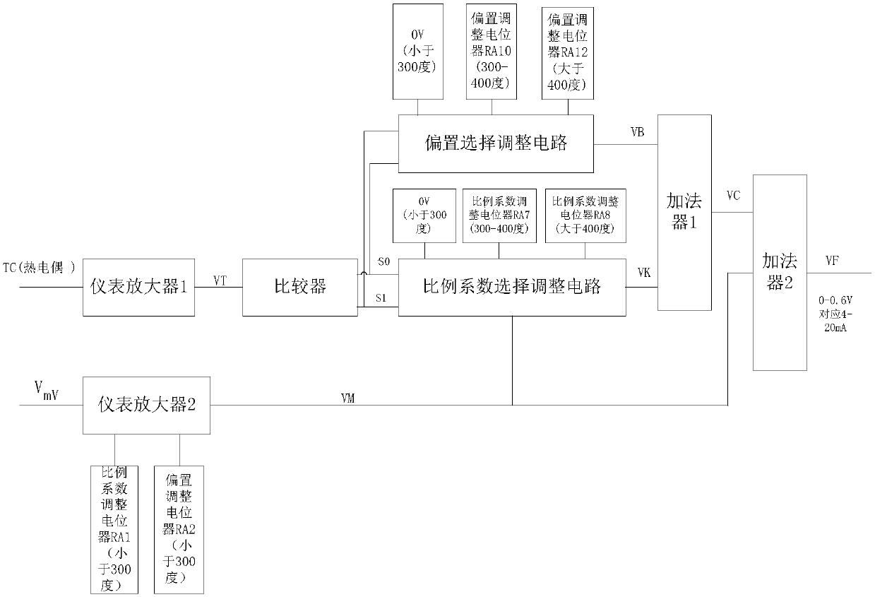
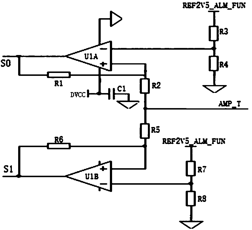
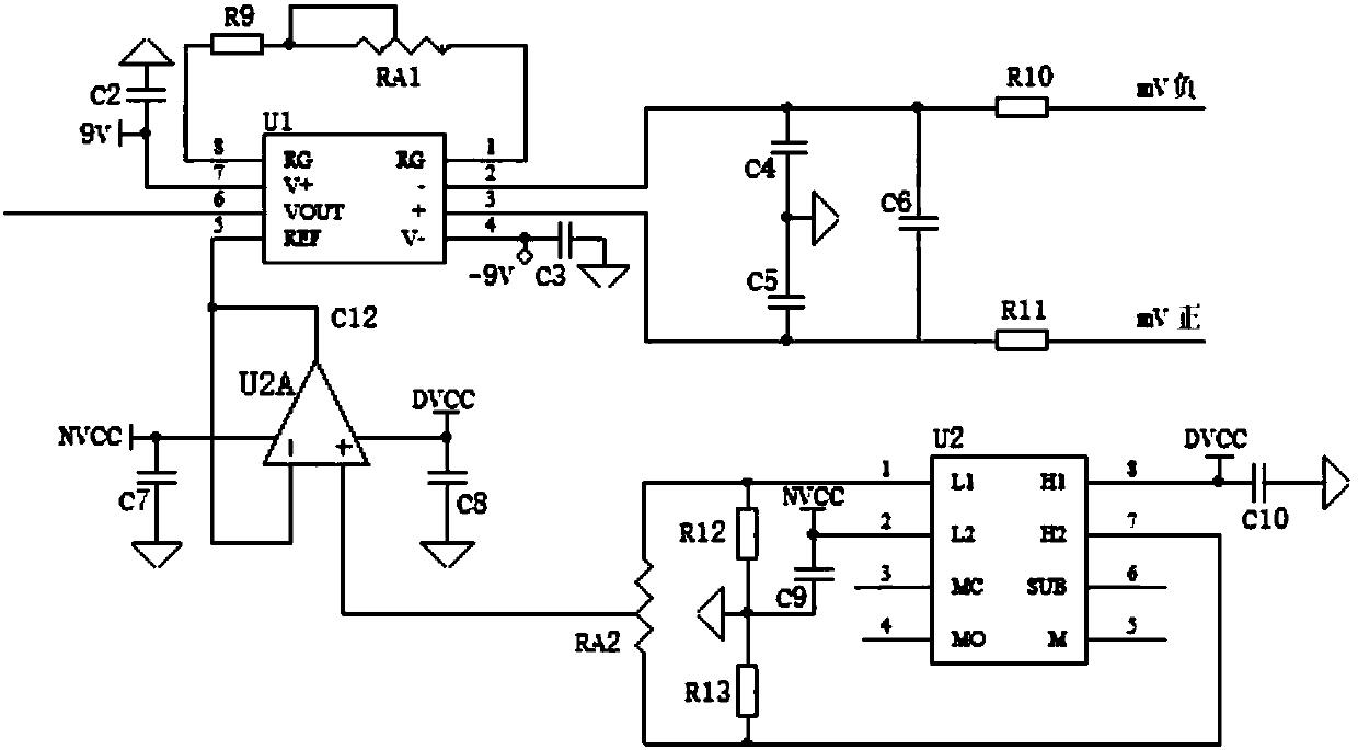
[0030] see Figure 1-5 . It should be noted that the structures, proportions, sizes, etc. shown in the drawings attached to this specification are only used to match the content disclosed in the specification, for those who are familiar with this technology to understand and read, and are not used to limit the implementation of the present invention. Limiting conditions, so there is no technical substantive meaning, any modification of structure, change of proportional relationship or adjustment of size, without affecting the effect and purpose of the present invention, should still fall within the scope of the present invention. within the scope covered by the disclosed technical content. At the same time, terms ...


PUM


Abstract

The invention provides an mV signal measurement temperature compensation device. The compensation device comprises an instrumentation amplifier I for amplifying an output voltage of a thermocouple, aninstrumentation amplifier II for amplifying the output voltage of a primary sensor, a comparator circuit, a bias selection adjustment circuit, a proportionality coefficient selection adjustment circuit, an adder I and an adder II; the comparator circuit outputs a signal S0 and a signal S1 after performing comparison processing on output signals of the instrumentation amplifier I, and the signal S0 and the signal S1 are respectively used as input signals of the proportionality coefficient selection adjustment circuit and the bias selection adjustment circuit; and the output of the bias selection adjustment circuit and the output of the proportionality coefficient selection adjustment circuit are used as the input of the adder I, and the output of the adder I and the output of the instrumentation amplifier I are used as the input of the instrumentation amplifier II.

Description

technical field [0001] The invention relates to the field of permanent magnet electromagnetic flowmeters, in particular to a temperature compensation device for mV signal measurement. Background technique [0002] According to the principle of permanent magnet electromagnetic flowmeter: E=B*L*V (1) [0003] Among them, E is the output mV signal of the primary sensor, B is the magnetic flux density of the permanent magnet, L is the diameter of the sodium pipe, and V is the flow rate of the sodium solution. Ideally, B and L will not change, and the mV potential output by the primary sensor has a linear relationship with the flow rate of sodium solution. However, in actual working conditions, since the diameter L of the pipe will change with the temperature of the sodium liquid due to thermal expansion and contraction, the value of B will decrease with the increase of temperature, and will also change with time. The secondary instrument should compensate for this due to temper...

Claims


Application Information

Patent Timeline
Patent Type & Authority Applications(China)
IPC IPC(8): G01F15/02G01F1/58
CPCG01F1/58G01F15/02G01F15/022
Inventor 赵俊奎
Owner CHONGQING CHUANYI AUTOMATION
Why Eureka
Try Eureka