Switchable gear clutch

A gear clutch, gear ring technology, applied in the direction of clutch, intermeshing clutch, mechanical drive clutch, etc., can solve the problem that the teeth cannot be fully overlapped.

Pending Publication Date: 2019-12-03
HOERBIGER ANTRIEBSTECHN HLDG
View PDF0 Cites 0 Cited by
  • Summary
  • Abstract
  • Description
  • Claims
  • Application Information

AI Technical Summary

Problems solved by technology

With a given diameter of these toothings, the necessary contact surfaces can be achieved only by a defined switching path, that is to say by a defined axial slippage of the shaft relative to the hub or vice versa, which however requires a certain switching Itinerary, the switching of the itinerary requires a certain switching time
However, if the switching process has to be carried out particularly quickly, then it is possible that sufficient toothing cannot be achieved within the available time

Method used


Image

  • Switchable gear clutch
  • Switchable gear clutch
  • Switchable gear clutch

Examples


Embodiment Construction

[0020] figure 1 A tooth clutch according to the prior art is shown, which has a shaft 10 which carries an external toothing 12 which is cut into the shaft. The hub 14 has a corresponding internal toothing 16 . Shaft 10 or hub 14 can be moved axially towards the respective other part via actuator 18 (see figure 1 double arrow in ), so that the teeth 12, 16 mesh with each other and can transmit torque.

[0021] from figure 1 It can be easily seen from the figure that in order to completely or at least partially shift the toothing 12 , 16 in an alternating manner, a relatively large switching path and thus a long switching time are required.

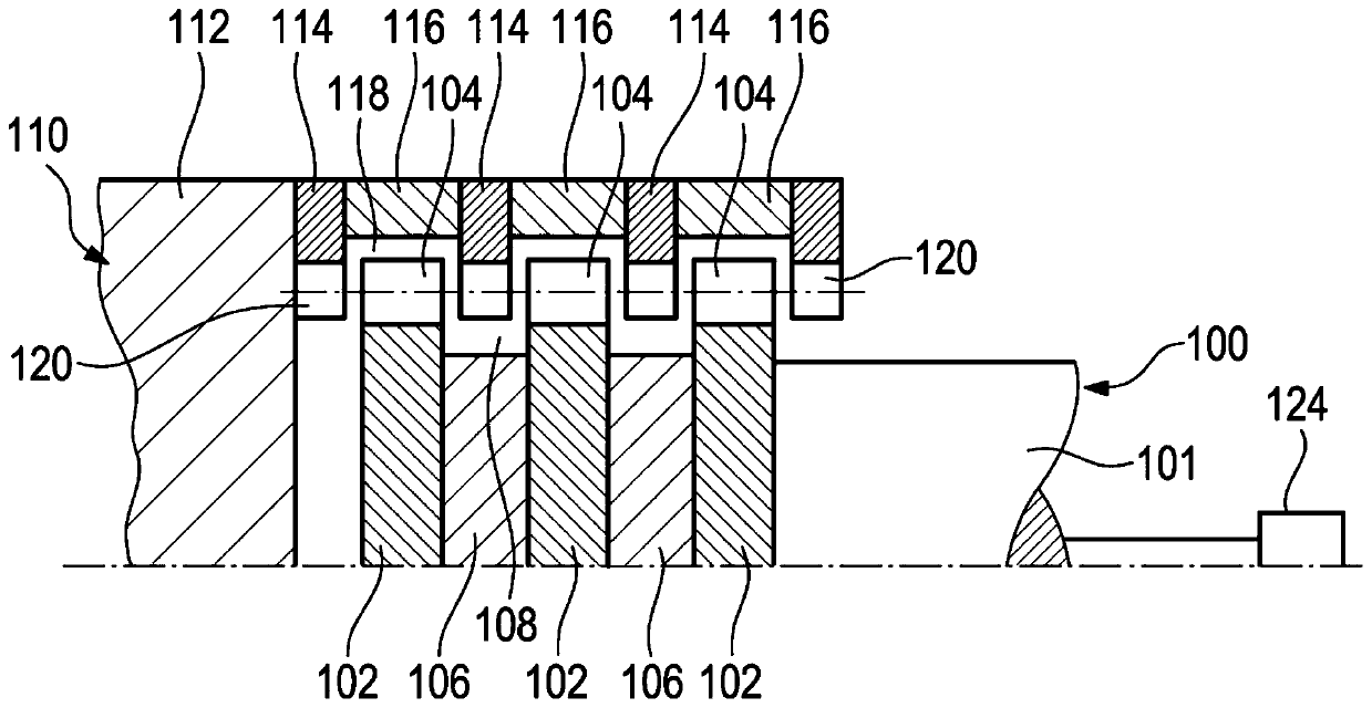
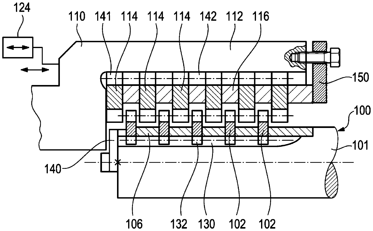
[0022] figure 2 shows a switchable dog clutch in which the figure 1 The toothing 12 , 16 shown is divided so to speak into individual toothings spaced apart from one another.

[0023] The shaft 100 has a shaft body 101 . The shaft carries or has a plurality of toothed rings 102 which are preferably designed as one piece and each hav...


PUM


Abstract

The invention relates to a switchable gear clutch, which comprise a shaft (100). Multiple ring gears (102), which are separated from each other, are arranged on the shaft. In a non-switch position, the ring gears (114) of the wheel hub (110) are arranged among the gear rings.

Description

technical field [0001] The invention relates to a switchable tooth clutch comprising a shaft and a hub, wherein the shaft has an external toothing and the hub has a corresponding internal toothing, and the shaft and the hub are axially in a disconnected position and Slidable relative to each other between coupling positions in which the external toothing is disengaged from the internal toothing and in which coupling the external toothing and the internal toothing are for torque transmission And move along the axial staggered. Background technique [0002] The external toothing and the internal toothing are designed such that in the coupling position the internal toothing meshes with the external toothing over the entire circumference. [0003] In such axially shiftable tooth clutches which are installed in drive trains which have to transmit high torques, a fast shifting process is often also required. A minimum total contact surface of the toothing is required for torque ...

Claims


Application Information

Patent Timeline
Patent Type & Authority Applications(China)
IPC IPC(8): F16D11/14
CPCF16D11/14
Inventor 安斯加尔·达姆
Owner HOERBIGER ANTRIEBSTECHN HLDG
Why Eureka
Try Eureka