Safe ventilated window

A ventilation window and safety-type technology, applied in windows/doors, door/window applications, soundproof doors/windows, etc., can solve the problems of poor safety of ventilation windows, achieve the effect of increasing coverage, improving ventilation effect, and reducing impact

Active Publication Date: 2019-12-03
扬州耐盾门窗幕墙有限公司
View PDF5 Cites 1 Cited by
  • Summary
  • Abstract
  • Description
  • Claims
  • Application Information

AI Technical Summary

Problems solved by technology

[0004] The purpose of the present invention is to solve the problem of poor safety of existing ventilation windows, and to provide a safety ventilation window with simple operation.

Method used


Image

  • Safe ventilated window
  • Safe ventilated window
  • Safe ventilated window

Examples


Embodiment 1

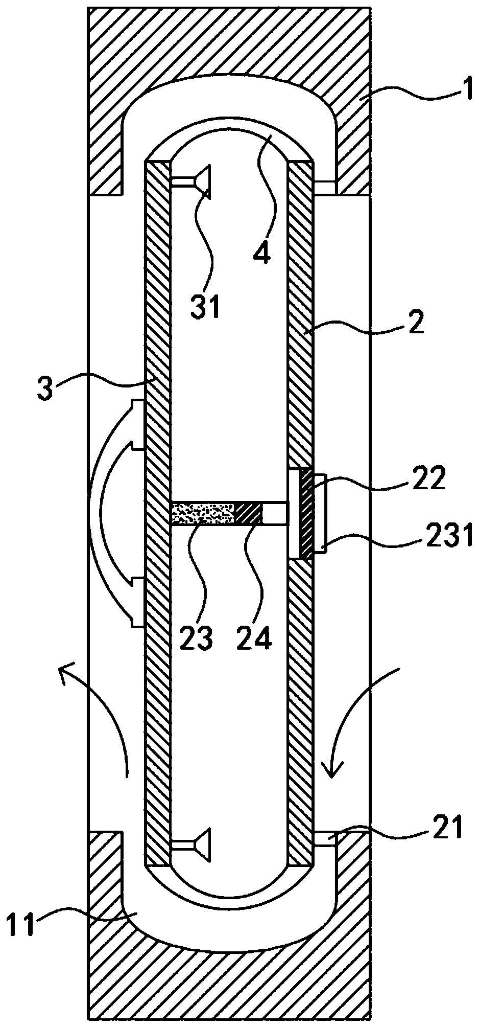
[0021] Such as Figure 1-2 As shown, a safety ventilating window includes a window frame 1, the inner peripheral side wall of the window frame 1 is provided with a depression 11, the depression 11 is a smooth arc groove on the inner wall, and the window frame 1 is provided with outer windows arranged side by side. The panel 2 and the inner window panel 3, it should be noted that the inner side wall of the inner window panel 3 is equipped with a handle for easy operation, and the inner window panel 3 and the outer window panel 2 are sealed and connected with outwardly protruding elastic parts along the peripheral side walls. The belt 4 and the elastic belt 4 can be made of rubber. When the elastic belt 4 is squeezed, it protrudes outward and fits the side wall of the depression 11. The outer side wall of the outer window panel 2 is fixed to the side wall of the depression 11 through the connecting strip 21. Connection, the center of the outer window panel 2 is fixedly connected...

Embodiment 2

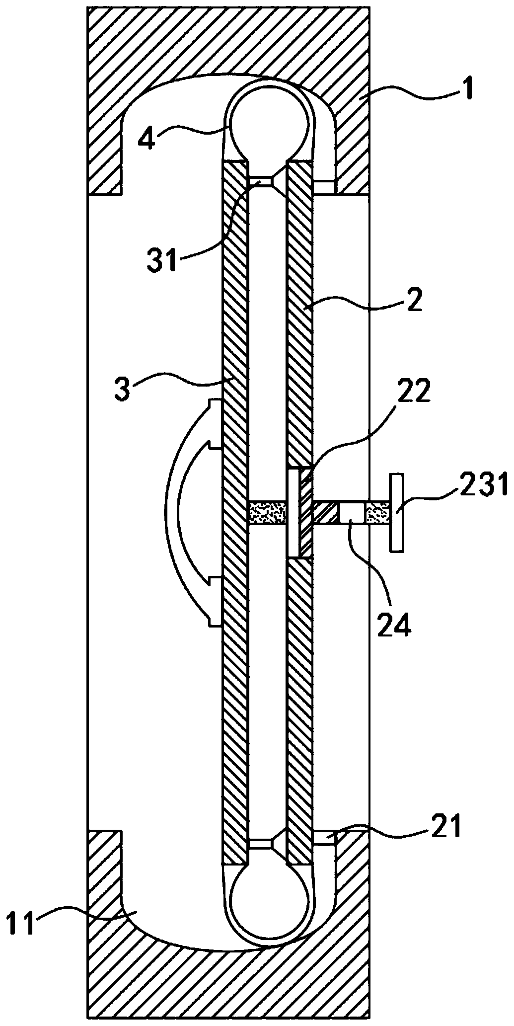
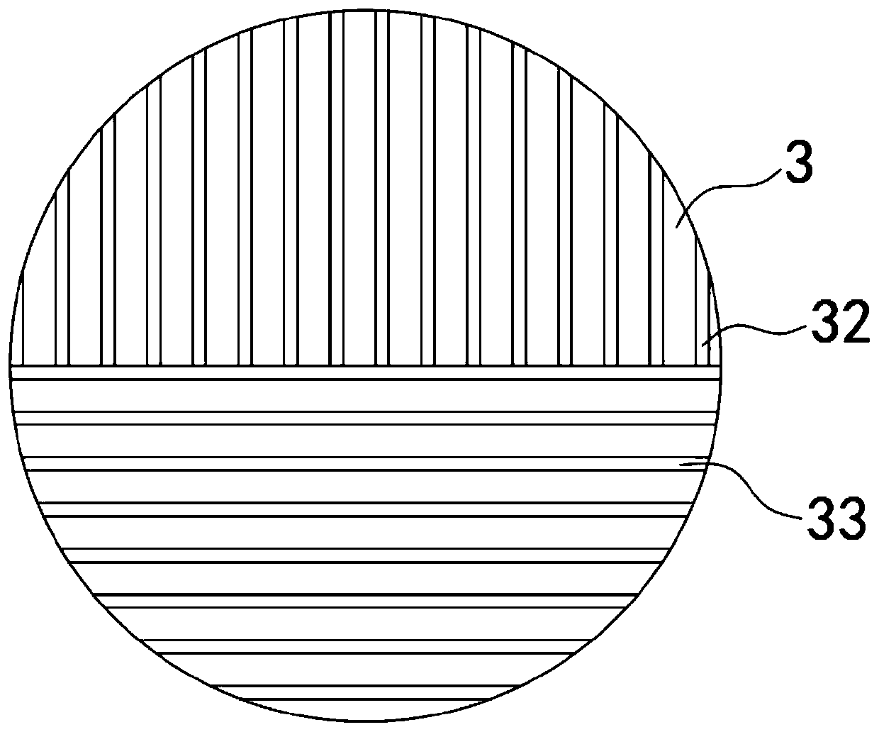
[0026] Such as Figure 3-6 As shown, the difference between this embodiment and Embodiment 1 is that the outer window panel 2 is composed of a circular frame 25 and a circular plate 26 sliding and sealingly connected in the circular frame 25, and the connecting block 22 is concentric with the circular plate 26 The disc block body that is provided with, the inner side wall of connecting block 22 is provided with threaded groove 221, and the surface of sliding rod 23 is engraved with the external screw thread that matches with threaded groove 221, can drive connecting when sliding rod 23 moves along its axis. The block 22 rotates 180 degrees around the axis; the upper half of the circular plate 26 and the inner window panel 3 is provided with a vertical light-blocking strip 32, and the lower half is provided with a horizontal light-blocking strip 33, and the circular plate 26 and the inner window panel 3 are in the In the separated state, the vertical light blocking bars 32 corr...


PUM


Abstract

The invention belongs to the field of building facilities, and in particular relates to a safe ventilated window. The safe ventilated window comprises a window frame, and a pit is formed in the side wall of the inner circumference of the window frame. An outer window plate and an inner window plate are arranged in the window frame side by side, and the inner window plate and the outer window plateare connected with a protruding elastic band in a sealing mode along the circumferential side wall. The elastic band protrudes outwards and attaches to the side wall of the pit when being extruded, and the outer side wall of the outer window plate is fixedly connected with the side wall of the pit through a connecting strip. The center of the outer window plate is fixedly connected with a connecting block made of a magnetic material, and the direction of the magnetic pole of the connecting block is orthogonal to the outer window plate. A sliding rod is glidingly connected in the connecting block in a penetrating mode. one end of the sliding rod is fixedly connected with the outer side wall of the inner window plate, and a limiting block used for limiting the connecting block is fixedly arranged at the other end of the sliding rod. The safe ventilated window can avoid a large gap between the window plates and the window frame, and therefore the safety of the ventilated window is improved. Meanwhile, as air enters a room through the sides of the window frame, the wind coverage can be increased, and the ventilation effect can be improved.

Description

technical field [0001] The invention belongs to the field of building facilities, in particular to a safety ventilation window. Background technique [0002] Existing windows, especially windows for glass curtain walls, are mostly top-hung windows. After opening, there is a large gap between the window panel and the window frame. When the external wind is strong, according to Bernoulli's law " The greater the flow velocity, the lower the pressure." It can be seen that light and small objects near the window and flower pots are susceptible to suction from the outside, which may not only cause the danger of falling objects from high altitudes, but also easily cause damage to indoor paper documents. Office personnel bring losses; in addition, because the lower gap of the top-hung window is relatively large, children also have certain dangers when playing, and the safety is not high. [0003] For this reason, we propose a kind of safe ventilating window to solve the above-menti...

Claims


Application Information

Patent Timeline
Patent Type & Authority Applications(China)
IPC IPC(8): E06B7/02E06B5/20E06B9/28E06B9/36
CPCE06B5/205E06B7/02E06B9/28E06B9/36
Inventor 曹亚涛
Owner 扬州耐盾门窗幕墙有限公司
Why Eureka
Try Eureka