
Fingerprint identification structure, fingerprint identification display device and driving method

A fingerprint identification and display device technology, which is applied in the direction of acquiring/arranging fingerprints/palmprints, character and pattern recognition, instruments, etc., can solve the problems of prolonged lighting interval time and fingerprint collection time, shortening the interval time and eliminating Afterimage effect, efficiency improvement effect

Active Publication Date: 2022-08-05
BOE TECH GRP CO LTD
View PDF7 Cites 0 Cited by
  • Summary
  • Abstract
  • Description
  • Claims
  • Application Information

AI Technical Summary

Problems solved by technology

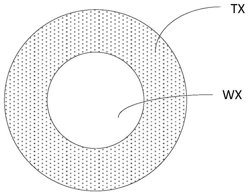
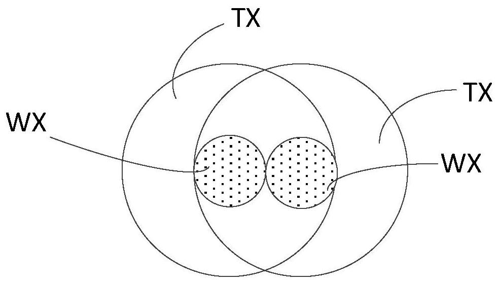
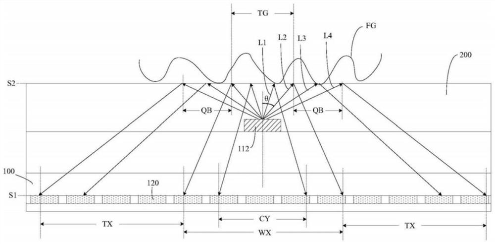
If you want to get a complete fingerprint image, you need to fill the non-imaging area. In order to solve this problem, you can use two point light sources to achieve complementary imaging, to achieve image complementation and fingerprint imaging, but because the image formed by two point light sources The middle and part of the imaging areas overlap with each other, and need to be lit in time-sharing, and because of the afterimage problem (lag) of the photosensitive sensor (sensor), when the light source is turned on for the second time, the reception of light information by the photosensitive sensor will be affected by the first point. The influence of the photosensitive sensor on the reception of light information in the case of bright light sources leads to the fact that in order to eliminate afterimages, it is necessary to wait for the second point light source to be lit to collect light information after the afterimages are over. The time is extended, and the fingerprint collection time is greatly extended

Method used


Image

  • Fingerprint identification structure, fingerprint identification display device and driving method
  • Fingerprint identification structure, fingerprint identification display device and driving method
  • Fingerprint identification structure, fingerprint identification display device and driving method

Examples


Embodiment Construction

[0039] In order to make the purpose, technical solutions and advantages of the embodiments of the present invention clearer, the technical solutions of the embodiments of the present invention will be clearly and completely described below with reference to the accompanying drawings of the embodiments of the present invention. Obviously, the described embodiments are some, but not all, embodiments of the present invention. Based on the described embodiments of the present invention, all other embodiments obtained by those of ordinary skill in the art fall within the protection scope of the present invention.

[0040] In the description of the present invention, it should be noted that the terms "center", "upper", "lower", "left", "right", "vertical", "horizontal", "inner", "outer", etc. The indicated orientation or positional relationship is based on the orientation or positional relationship shown in the accompanying drawings, which is only for the convenience of describing t...


PUM


Abstract

The invention relates to a fingerprint identification structure, comprising a sensing electrode arranged on a substrate, the sensing electrode comprising mutually insulated first sub-sensing electrodes and a plurality of second sub-sensing electrodes with the same number as that of a plurality of point light sources. The photosensitive unit includes a first photosensitive response unit group correspondingly connected with the first sub-sensing electrodes and a second photosensitive response unit group correspondingly connected with a plurality of second sub-sensing electrodes; the first fixed voltage is provided to the first sub-sensing electrodes to make The photosensitive response units in the first photosensitive response unit group are in a working state; a first voltage is provided to the second sub-sensing electrodes corresponding to the lighted point light source group, so that the corresponding part of the photosensitive response units are in an off state, and the corresponding light-sensitive response units are in an off state, and the corresponding light-sensitive response units are in an off state. The second sub-sensing electrode of the lit point light source group provides a first fixed voltage, so that the corresponding other part of the light-sensitive response unit is in a working state. The invention also relates to a fingerprint identification display device and a driving method thereof.

Description

technical field [0001] The present invention relates to the field of display technology, in particular to a fingerprint identification structure, a fingerprint identification display device and a driving method. Background technique [0002] Fingerprint recognition is a technology for identification by comparing the minutiae points of different fingerprints. Everyone's fingerprints are different, and there are obvious differences between the ten fingers of the same person, so fingerprints can be used for identification. At present, more and more terminal devices are equipped with fingerprint identification modules, and most of them use optical fingerprint collection. The light source is a point light source, but the image formed by lighting a point light source includes two areas: one area is a non-imaging area, The fingerprint is not imaged in this area, and the other area is the imaging area, and the fingerprint can be imaged in this area. If you want to get a complete f...

Claims


Application Information

Patent Timeline
Patent Type & Authority Patents(China)
IPC IPC(8): G06V40/13G06F3/042H01L27/32
CPCG06F3/042G06V40/1318H10K59/40
Inventor 丁小梁王海生刘英明王佳斌李亚鹏
Owner BOE TECH GRP CO LTD
Learn More