
Multi-floater wave energy driven power generation device based on modular truss platform

A power generation device and truss platform technology, which is applied in ocean energy power generation, floating buildings, transportation and packaging, etc., can solve the problems of affecting the power generation of buoys on the back wave side, reducing power generation, and unfavorable energy stable output, etc., to achieve easy large-scale The effect of scale promotion, increasing power generation, and improving energy utilization

Pending Publication Date: 2019-11-29
HARBIN INST OF TECH AT WEIHAI +3
View PDF7 Cites 7 Cited by
  • Summary
  • Abstract
  • Description
  • Claims
  • Application Information

AI Technical Summary

Problems solved by technology

This device captures wave energy through the heave motion of multiple floats arranged side by side. However, due to the short distance between the floats, the float on the front wave side, especially in the case of short waves, will have a shielding effect on the float on the back wave side, which seriously affects the back wave. Generating power of side float
In addition, complex wave interference will also occur between the floats, which will reduce the power generation in severe cases and is not conducive to the stable output of energy

Method used


Image

  • Multi-floater wave energy driven power generation device based on modular truss platform
  • Multi-floater wave energy driven power generation device based on modular truss platform
  • Multi-floater wave energy driven power generation device based on modular truss platform

Examples


Embodiment

[0046] Example: Combine Figure 1-Figure 11 , a multi-floor wave energy generating device based on a truss platform in this embodiment is further elaborated:

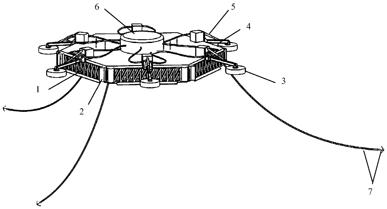
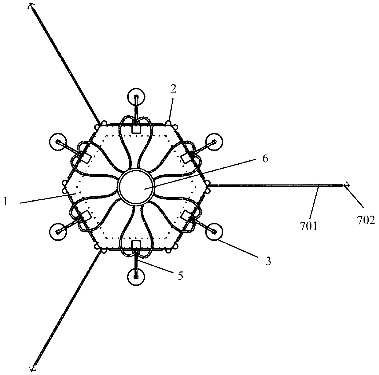
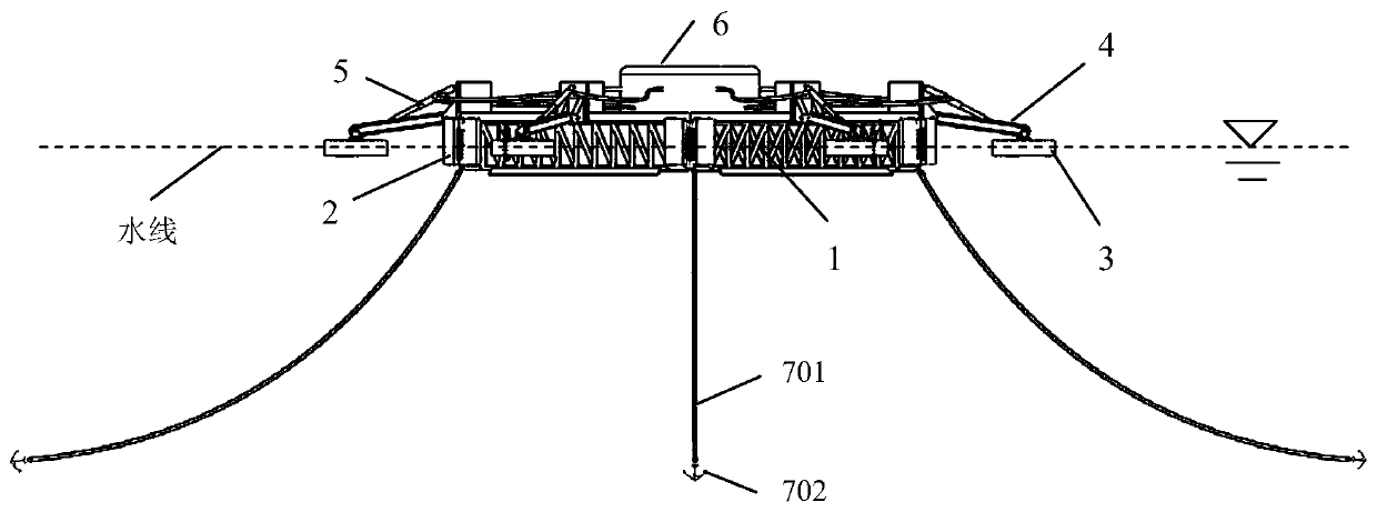
[0047] A multi-floor wave energy generation device based on a truss platform, see figure 1 , the device includes a truss platform 1, a buoyancy block 2, a float 3, a connecting rod 4, a hydraulic transmission device 5, a generator set 6 and an anchoring system 7; Bearing structure; the buoyancy block 2 is installed on the side of the truss platform 1 to provide buoyancy for the entire power generation device; the buoy 3 and the truss platform 1 are connected by the connecting rod 4; the hydraulic transmission device 5 is respectively connected to the connecting rod 4; the generator set 6 Placed on the upper deck of the truss platform 1 to generate electric energy; the mooring system 7 is used for the positioning of the power generation device.

[0048] see figure 2 , the truss-type platform 1 adopts a regular hexago...


PUM


Abstract

The invention provides a multi-floater wave energy driven power generation device based on a modular truss platform, belongs to the field of wave energy driven power generation and ocean engineering equipment and solves the technical problems that the energy utilization efficiency of a unit-area sea area is low, the construction cost of a unit-capacity generator set is high, floaters are shieldedmutually, and the wave permeation property of the platform is poor, of an existing oscillating floater type wave energy driven power generation device. The multi-floater wave energy driven power generation device is characterized in that the truss platform is of a regular polygonal structure and provides a bearing platform for the overall power generation device; a plurality of floating blocks areinstalled on the side surface of the truss platform and are used for providing floating force for the overall power generation device; a plurality of floaters are uniformly distributed surrounding the truss platform in a planetary form and are connected with the truss platform by adopting connecting rods; hydraulic transmission devices are correspondingly connected with the connecting rods; a generator set is placed on an upper deck of the truss platform; all floaters share one generator set for generating power; and a mooring system is used for positioning the overall power generation device. The multi-floater wave energy driven power generation device provided by the invention is especially applicable to power supply of offshore equipment, islands and the like.

Description

technical field [0001] The invention relates to a wave energy generating device, in particular to a multi-floor wave energy generating device based on a modular truss platform, which belongs to the field of wave energy generating and ocean engineering equipment. Background technique [0002] Energy consumption and environmental pollution have always been the key issues restricting human development. Due to the problems of environmental pollution and energy shortage, the development and utilization of renewable energy has attracted more and more attention from countries. Wave energy is a kind of renewable green energy, which has received extensive attention due to its advantages such as wide distribution and large reserves. The development of wave energy is of great significance and has broad application prospects. It can be used for: [0003] (1) Power supply for deep-sea cage culture and marine instrumentation equipment; [0004] (2) Military, production and domestic powe...

Claims


Application Information

Patent Timeline
Patent Type & Authority Applications(China)
IPC IPC(8): F03B13/18B63B35/44B63B21/50
CPCB63B21/50B63B35/44B63B2021/505B63B2035/4466F03B13/1815F03B13/189Y02E10/30
Inventor 何广华张志刚栾政晓耿宝磊金瑞佳宋学刚彭爱武
Owner HARBIN INST OF TECH AT WEIHAI
Learn More