A method for adjusting orbit attitude coupling for deorbit delivery of low-orbit space debris with geomagnetic energy storage

A space debris and coupling adjustment technology, which is applied to space navigation equipment, space navigation equipment, space navigation aircraft, etc., can solve the problems of continuous interruption of energy storage and energy release, and achieve efficiency and economical problems Improved effect

Active Publication Date: 2021-07-02
INST OF MECHANICS - CHINESE ACAD OF SCI
View PDF0 Cites 0 Cited by
  • Summary
  • Abstract
  • Description
  • Claims
  • Application Information

AI Technical Summary

Problems solved by technology

[0010] To this end, the embodiment of the present invention provides a method for adjusting the orbit-attitude coupling of geomagnetic energy storage for low-orbit space debris off-orbit delivery to solve the prob

Method used


Image

  • A method for adjusting orbit attitude coupling for deorbit delivery of low-orbit space debris with geomagnetic energy storage
  • A method for adjusting orbit attitude coupling for deorbit delivery of low-orbit space debris with geomagnetic energy storage
  • A method for adjusting orbit attitude coupling for deorbit delivery of low-orbit space debris with geomagnetic energy storage

Examples


Embodiment 1

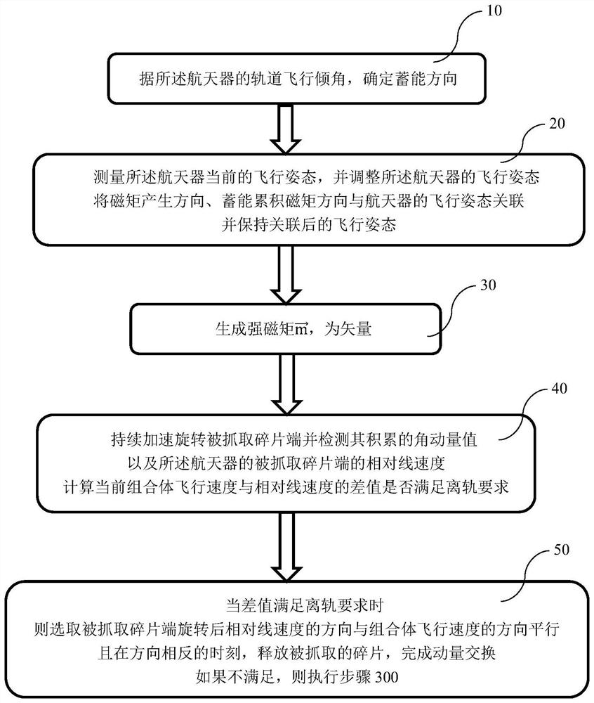
[0047] Such as figure 1 and figure 2 As shown, the present invention provides a geomagnetic energy storage low-orbit space debris off-orbit control method, and the space debris is captured by the spacecraft for geomagnetic energy storage. The geomagnetic energy storage includes the following steps:

[0048] Step 10. Determine the energy storage direction according to the orbital inclination of the spacecraft;

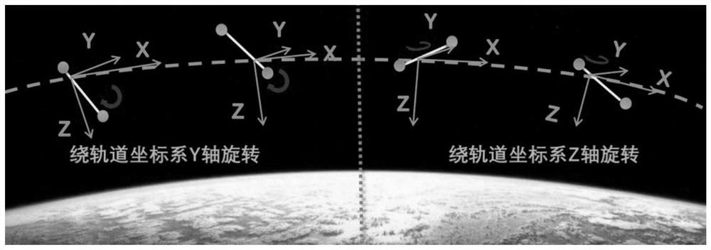
[0049] When the inclination angle of the orbital flight of the spacecraft is greater than the set angle, energy accumulation is carried out around the y-axis of the orbital plane;

[0050] When the orbital inclination is smaller than the set angle, energy accumulation is carried out around the z-axis of the orbital plane.

[0051] Wherein, energy storage accumulation in this embodiment specifically refers to continuous acceleration in a preset direction, which needs to continuously generate magnetic torque in the preset direction, so that the speed in this direction ...

Embodiment 2

[0070] For Embodiment 1 of the present invention, further, the basic expression of the rotational torque received by the magnet in the magnetic field is:

[0071] L=m×B (4)

[0072] In the formula (4), L is the magnetic moment vector, m is the magnetic moment vector carried by the spacecraft, and B is the magnetic induction intensity vector of the earth's space magnetic field.

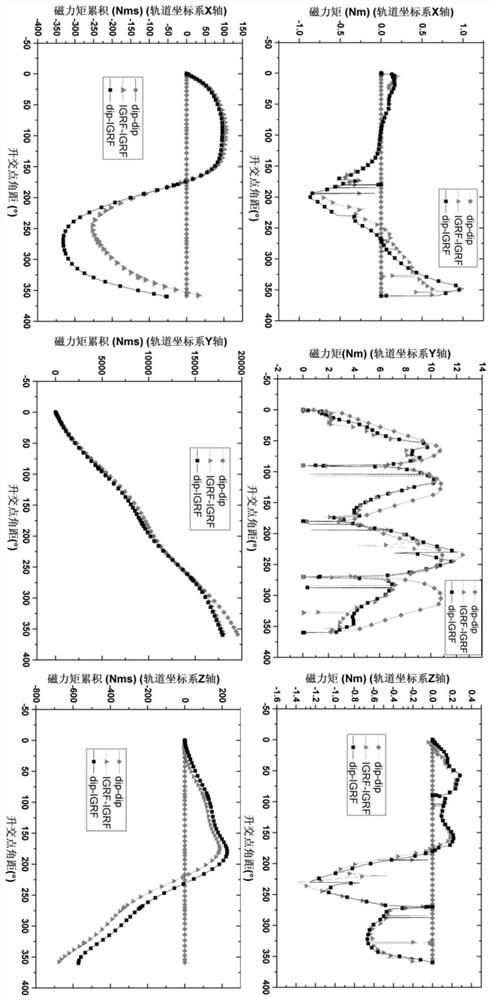
[0073] For example: next image 3 The middle is the magnetic moment and the magnetic moment accumulation around the X-axis, Y-axis, and Z-axis while accumulating energy around the Y-axis of the orbital coordinate system in one orbital period, image 3 The left, middle, and right of , represent the magnetic moments of the X-axis, Y-axis, and Z-axis, respectively. image 3 The left, middle, and right of , represent the cumulative magnetic moment of the X-axis, Y-axis, and Z-axis, respectively.

[0074] In theory, it will only accumulate on the Y axis, and the others are 0, corresponding to the dip-dip...


PUM


Abstract

The embodiment of the present invention discloses a geomagnetic energy storage low orbit space debris off-orbit delivery orbit attitude coupling adjustment method, which includes the following steps: Step 100, decomposing the entire geomagnetic energy storage low orbit period into energy gathering arcs and energy releasing arcs section, and configure the momentum wheel energy-absorbing device on the three axes of the spacecraft; step 200, respectively determine the energy-gathering arc section and the energy-discharging arc section when the spacecraft performs energy storage and accumulation around the y-axis of the orbital plane and the z-axis of the orbital plane; Step 300, after determining the energy-gathering arc segment, for the energy storage targets of different orbital coordinate systems Y-axis or Z-axis, complete the de-orbiting operation of space debris based on the geomagnetic energy storage low-orbit space debris de-orbiting control method; Step 400, After the energy release arc is determined, the three-axis momentum wheel energy absorbing device of the spacecraft is unloaded through the generated magnetic moment.

Description

technical field [0001] Embodiments of the present invention relate to the technical field of space debris de-orbiting, and in particular to a method for adjusting the orbit-attitude coupling of geomagnetic energy storage low-orbit space debris de-orbiting delivery. Background technique [0002] Space junk with a diameter of 10cm can pose a serious threat to spacecraft and astronauts. The Hubble Telescope, the Space Shuttle, and the International Space Station have all been hit by space debris; The probability of a threat increases rapidly, (Kessler effect: more space debris is created due to the impact of space debris). [0003] The Kessler effect further aggravates the threat of space debris. For example, in 2009, the abandoned Comos satellite of Russia collided with the Iridum satellite of the United States, resulting in more than 2,000 space debris. If the existing space debris cannot be actively and effectively removed, the space debris will continue to increase signific...

Claims


Application Information

Patent Timeline
IPC IPC(8): B64G1/24B64G1/66
CPCB64G1/242B64G1/66B64G1/245
Inventor 李文皓冯冠华张珩
Owner INST OF MECHANICS - CHINESE ACAD OF SCI
Why Eureka
Try Eureka