
Welding device and operation steps of drum cover and connecting shaft of corn thresher

A welding device and roller cover technology, applied in welding equipment, auxiliary devices, tin feeding devices, etc., can solve problems such as increased bending stress, high noise, and low efficiency

Active Publication Date: 2021-01-22
ANYANG INST OF TECH
View PDF10 Cites 0 Cited by
  • Summary
  • Abstract
  • Description
  • Claims
  • Application Information

AI Technical Summary

Problems solved by technology

[0002] my country is a big corn planting country. Corn threshers need to be used for threshing after corn matures. The current corn threshers are more common in drum structure, such as the patent name A kind of elastic corn threshing drum and corn thresher (CN207321977U), and the patent The name corn threshing drum device (CN207054111U) adopts a drum-type structure, and threshing is realized by extruding corn through the protrusions on the drum and the outside of the drum. Both ends of the drum are equipped with a drum cover, and the connecting shaft is welded on the drum cover. The drum cover, connecting shaft and drum must have a certain degree of coaxiality, otherwise the drum will be eccentric, the gap between the corn and the drum will change in the drum shell, and the drum gap will be blocked, and the drum will not continue to rotate and damage the motor, and both sides When the coaxiality between the roller cover and the connecting shaft does not meet the requirements, the additional bending stress of the supporting shafts on both sides will increase, resulting in high noise and low efficiency

Method used


Image

  • Welding device and operation steps of drum cover and connecting shaft of corn thresher
  • Welding device and operation steps of drum cover and connecting shaft of corn thresher
  • Welding device and operation steps of drum cover and connecting shaft of corn thresher

Examples


Embodiment Construction

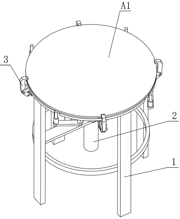
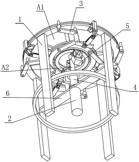
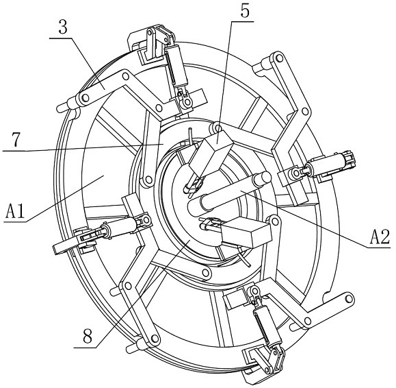
[0043] combine Figure 1-11 , a welding device for a drum cover and a connecting shaft of a corn thresher according to the present invention, comprising a welding base frame 1, a clamping cylinder 2, a synchronous centering fixing mechanism 3, a centering sleeve 4, a welding mechanism 5, and a supporting beam 6 , Outer turntable 7, inner turntable 8, described synchronous centering fixing mechanism 3 comprises column pin one 301, connecting rod 302, centering pin 303, swing bar 304, column pin two 305, pressing bar 306, pressing bar support 307, column pin three 308, column pin four 309, column pin five 310, elastic connecting rod 311, column pin six 312, connecting block 313, column pin seven 314, slide block 315, described welding mechanism 5 comprises welding cylinder frame 501, welding torch cylinder 502, welding torch holder 503, welding torch 504, the direction toward the central axis of the drum cover A1 is defined as the inner side, and vice versa is defined as the out...


PUM

PropertyMeasurementUnit
angleaaaaaaaaaa

Abstract

The invention discloses a welding device for a roller cover and a connecting shaft of a corn thresher. The welding device comprises a welding base frame, wherein an inner rotating table and an outer rotating table are coaxially and fixedly arranged on the welding base frame, and four synchronous centering fixing mechanisms are uniformly distributed and arranged on the outer rotating table in the circumferential direction; the synchronous centering fixing mechanisms comprise connecting rods and swing rods, wherein one ends of the connecting rods are hinged to the outer rotating table; the swingrods are of structures in which each of two parallel edges are connected through one bevel edge, and one parallel edges of the swing rods and the corner positions of the bevel edges are hinged to theother ends of the connecting rods; one parallel edges of the swing rods are connected with pressing rods used for pressing the roller cover, and the other parallel edges of the swing rods are fixedlyconnected with centering sleeves used for centering the roller cover; two welding mechanisms are uniformly and fixedly distributed on the inner rotating table in the circumferential direction, and acentering sleeve and a clamping air cylinder are fixed on the welding base frame; and an inner hole of the centering sleeve is matched with a clearance from the middle part of the connecting shaft tothe lower part of the connecting shaft in a sliding mode, and the upper end of a piston rod of the clamping air cylinder is positioned in the centering sleeve, so that centering and clamping of the roller cover and automatic circumference welding of the roller cover and the connecting shaft are realized at the same time.

Description

technical field [0001] The invention relates to the field of corn thresher processing equipment, in particular to a welding device and operation steps for a drum cover and a connecting shaft of a corn thresher. Background technique [0002] my country is a big corn planting country. Corn threshers need to be used for threshing after corn matures. The current corn threshers are more common in drum structure, such as the patent name A kind of elastic corn threshing drum and corn thresher (CN207321977U), and the patent The name corn threshing drum device (CN207054111U) adopts a drum-type structure, and threshing is realized by extruding corn through the protrusions on the drum and the outside of the drum. Both ends of the drum are equipped with a drum cover, and the connecting shaft is welded on the drum cover. The drum cover, connecting shaft and drum must have a certain degree of coaxiality, otherwise the drum will be eccentric, the gap between the corn and the drum will change...

Claims


Application Information

Patent Timeline
Patent Type & Authority Patents(China)
IPC IPC(8): B23K1/00B23K3/06B23K3/08
CPCB23K1/0008B23K3/063B23K3/087
Inventor 国秀丽张程焱吴贵军冯贺高素玲
Owner ANYANG INST OF TECH
Learn More