
Positioning and punching mold of automobile part

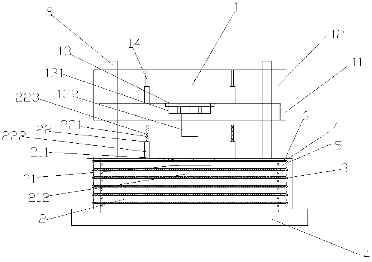
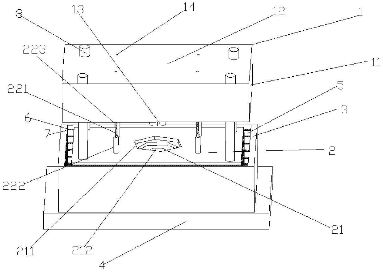
A technology for auto parts and positioning dies, which is applied in the field of stamping dies for auto parts, can solve problems such as low assembly efficiency, mold vibration, and slow production efficiency, and achieve the effects of simple structure, precise positioning, and vibration prevention

Inactive Publication Date: 2019-11-26
TIANJIN MOTOR DIES
View PDF0 Cites 3 Cited by
  • Summary
  • Abstract
  • Description
  • Claims
  • Application Information

AI Technical Summary

Problems solved by technology

In the manufacture of automobiles, some parts are usually obtained by stamping. Due to the great impact force of the punch on the mold during stamping, the mold will vibrate greatly at the moment of impact, which will cause vibration to both the material and the mold, and will cause Reduced machining accuracy of parts
At present, the positioning accuracy in the stamping process of auto parts is not accurate, resulting in low processing accuracy, slow production efficiency, low assembly efficiency, and greatly increased production costs.

Method used


Image

  • Positioning and punching mold of automobile part
  • Positioning and punching mold of automobile part

Examples


Embodiment Construction

[0015] It should be noted that, in the case of no conflict, the embodiments of the present invention and the features in the embodiments can be combined with each other.

[0016] In describing the present invention, it should be understood that the terms "center", "longitudinal", "transverse", "upper", "lower", "front", "rear", "left", "right", " The orientations or positional relationships indicated by "vertical", "horizontal", "top", "bottom", "inner" and "outer" are based on the orientations or positional relationships shown in the drawings, and are only for the convenience of describing the present invention and Simplified descriptions, rather than indicating or implying that the device or element referred to must have a particular orientation, be constructed and operate in a particular orientation, and thus should not be construed as limiting the invention. In addition, the terms "first", "second", etc. are used for descriptive purposes only, and should not be understood ...


PUM


Abstract

The invention provides a positioning and punching mold of an automobile part. The positioning and punching mold of the automobile part comprises an upper mold cover, a lower mold base, a positioning surrounding plate and a base plate, wherein the lower mold base is arranged on the base plate, the positioning surrounding plate is arranged on the periphery of the lower mold base, a fixed cavity is formed between the positioning surrounding plate and the lower mold base, the upper mold cover is arranged right above the lower mold base, the upper mold cover comprises a side plate matched with thefixed cavity, ball grooves are formed in the outer wall of the lower mold base and the inner wall of the positioning surrounding plate, and a plurality of balls are uniformly distributed in the ball grooves. According to the positioning and punching mold of the automobile part, the vibration of materials and a mold is effectively prevented, the positioning of the positioning and punching mold is accurate, and the structure is simple.

Description

technical field [0001] The invention relates to the field of stamping dies for auto parts, in particular to a positioning stamping die for auto parts. Background technique [0002] Stamping is a pressure processing method that uses a stamping die to apply pressure to a sheet on a press to cause plastic deformation or separation to obtain parts of the desired shape and size. In the manufacture of automobiles, some parts are usually obtained by stamping. Due to the great impact force of the punch on the mold during stamping, the mold will vibrate greatly at the moment of impact, which will cause vibration to both the material and the mold, and will cause The machining accuracy of parts is reduced. At present, inaccurate positioning accuracy in the stamping process of auto parts leads to low processing accuracy, slow production efficiency, low assembly efficiency, and greatly increases production costs. Contents of the invention [0003] In view of this, the present inventi...

Claims


Application Information

Patent Timeline
Patent Type & Authority Applications(China)
IPC IPC(8): B21D37/10B21D37/12
CPCB21D37/10B21D37/12
Inventor 任伟
Owner TIANJIN MOTOR DIES
Learn More