
Analysis method of three-dimensional impact load elastic-plastic bending crack tip plastic region

A flexural crack, impact load technique, applied in the research field of flexural crack propagation path

Pending Publication Date: 2019-11-22
ZHENGZHOU TECHN COLLEGE
View PDF2 Cites 3 Cited by
  • Summary
  • Abstract
  • Description
  • Claims
  • Application Information

AI Technical Summary

Problems solved by technology

[0002] So far, the research results on the fracture characteristics of bending cracks are mainly limited to two-dimensional linear elastic fracture, two-dimensional nonlinear elastic fracture and two-dimensional elastic-plastic fracture. The calculation of the dynamic stress field in the plastic region of the elastic-plastic bending crack tip of the crack body and the determination of the range of the dynamic plastic region have not yet been studied.

Method used


Image

  • Analysis method of three-dimensional impact load elastic-plastic bending crack tip plastic region
  • Analysis method of three-dimensional impact load elastic-plastic bending crack tip plastic region
  • Analysis method of three-dimensional impact load elastic-plastic bending crack tip plastic region

Examples


Embodiment 1

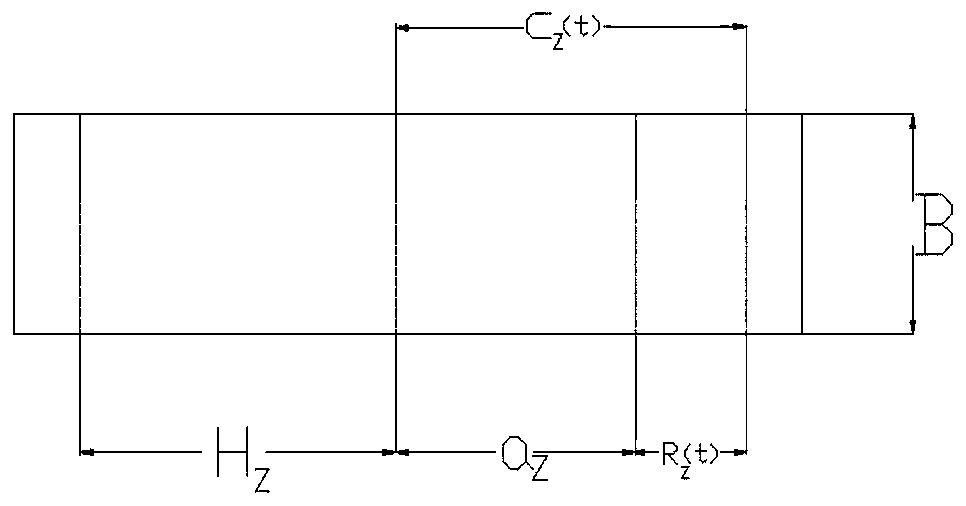
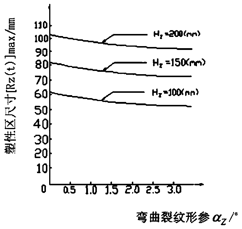
[0119] Taking carbon steel as an example, the Poisson's ratio of carbon steel is ν=0.23. When the impact load applied to the cracked body is: σ aZ (t) = 0.125σ s (4t-t 2 ), σ rZ (t) = 0.025σ s (4t-t 2 ), the numerical solution of the projection length of the maximum size of the dynamic plastic zone at the tip of the three-dimensional elastic-plastic bending crack on the extension line of the crack straight line can be calculated at t=2 seconds. Now, the numerical solution of the projection length of the maximum size of the dynamic plastic zone at the tip of the three-dimensional elastic-plastic bending crack on the extension line of the crack straight line is plotted as follows: Figure 2a-2e shown.

Embodiment 2

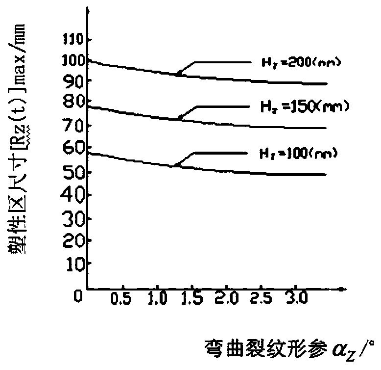
[0121] Taking alloy steel as an example, the Poisson's ratio of carbon steel is ν=0.3. When the impact load applied to the cracked body is: σ aZ (t) = 0.33σ s (2t-t 2 ), σ rZ (t) = 0.03σ s (2t-t 2 ), the numerical solution of the projection length of the maximum size of the dynamic plastic zone at the tip of the three-dimensional elastic-plastic bending crack on the extension line of the crack straight line at t=1 second can be calculated. Now, the numerical solution of the projection length of the maximum size of the dynamic plastic zone at the tip of the three-dimensional elastic-plastic bending crack on the extension line of the crack straight line is plotted as follows: Figures 3a-3e shown.

[0122] combined with Figure 2a-2e and 3a-3e, it can be seen that under the impact load of the same intensity and the same rate of change, the maximum size of the dynamic plastic zone of the three-dimensional bending crack corresponding to the same length of the straight line ...

Embodiment 3

[0125] Taking rolled aluminum as an example, the Poisson's ratio of rolled aluminum is ν=0.36. When the external impact loads acting on the cracked body are: σ aZ (t) = σ s [1-(t-3) 2 ], the numerical solution of the projection length of the maximum dimension of the dynamic plastic zone at the tip of the three-dimensional elastic-plastic bending crack on the extension line of the crack straight line can be calculated at t=3 seconds. Now, the numerical solution of the projection length of the maximum size of the dynamic plastic zone at the tip of the three-dimensional elastic-plastic bending crack on the extension line of the crack straight line is plotted as follows: Figures 4a-4e shown.

[0126] from Figures 4a-4eIt can be seen from the five groups of figures that the greater the thickness of the three-dimensional crack body, the larger the thickness of the three-dimensional crack body, for the same length of the straight line part of the crack and the same degree of be...


PUM

PropertyMeasurementUnit
Thicknessaaaaaaaaaa
Poisson's ratioaaaaaaaaaa

Abstract

The invention discloses an analysis method of a three-dimensional impact load elastic-plastic bending crack tip plastic region. The impact action stress is comprehensively considered; impact normal stress and impact shear stress are applied to the boundary of the three-dimensional plastic area; a dynamic plastic region of the tip of the three-dimensional elastic-plastic bending crack is calculatedby using a numerical solution; under the action of the same external load, the dynamic plastic region at the tip of the three-dimensional elastic-plastic bending crack is reduced along with the increase of the thickness of the three-dimensional crack body; along with the uniform increase of the thickness of the three-dimensional crack body, the maximum size of the plastic region at the tip of thethree-dimensional elastic-plastic bending crack is continuously decreased, the decreasing amplitude is smaller and smaller, and finally the maximum size of the plastic region at the tip of the elastic-plastic bending crack tends to the maximum size in a plane strain state. When the three-dimensional crack body has a geometric dimension phase, the maximum size value of the plastic region at the tip of the three-dimensional bent crack is gradually increased along with the continuous increase of the impact load. A brand-new theoretical model for calculating the dynamic plastic region of the three-dimensional elastic-plastic bending crack is established, and engineering practice can be more accurately served.

Description

technical field [0001] The invention relates to the research on the expansion path of the bending crack, in particular to the analysis method of the plastic zone of the elastoplastic bending crack tip under three-dimensional impact load. Background technique [0002] So far, the research results on the fracture characteristics of bending cracks are mainly limited to two-dimensional linear elastic fracture, two-dimensional nonlinear elastic fracture and two-dimensional elastic-plastic fracture. The calculation of the dynamic stress field in the plastic region of the elastic-plastic bending crack tip of the crack body and the determination of the range of the dynamic plastic region have not been studied so far. In engineering practice, the thickness of the crack body structure is often relatively large, and usually cannot be ignored. Therefore, it is very necessary to study the impact fracture characteristics of elastic-plastic bending cracks in three-dimensional cracked bodi...

Claims


Application Information

Patent Timeline
IPC IPC(8): G06F17/50G06T17/00
CPCG06T17/00Y02T90/00
Inventor 杨大鹏潘海洋党令军张平萍杨新华
Owner ZHENGZHOU TECHN COLLEGE
Learn More