Time sequence measurement method and device

A timing measurement and timing technology, applied in the field of measurement, can solve problems such as cumbersome operation, damaged components, and low test efficiency

Active Publication Date: 2019-11-22
DONGGUAN MENTECH OPTICAL & MAGNETIC CO LTD
View PDF6 Cites 1 Cited by
  • Summary
  • Abstract
  • Description
  • Claims
  • Application Information

AI Technical Summary

Problems solved by technology

[0006] The purpose of the present invention is to provide a timing measurement method and device to alleviate the technical problems of the existing timing measurement method such as tedious operation, low test efficiency, and even damage to components

Method used


Image

  • Time sequence measurement method and device
  • Time sequence measurement method and device
  • Time sequence measurement method and device

Examples


Embodiment 1

[0047] According to an embodiment of the present invention, an embodiment of a timing measurement method is provided. It should be noted that the steps shown in the flow chart of the accompanying drawings can be executed in a computer system such as a set of computer-executable instructions, and, Although a logical order is shown in the flowcharts, in some cases the steps shown or described may be performed in an order different from that shown or described herein.

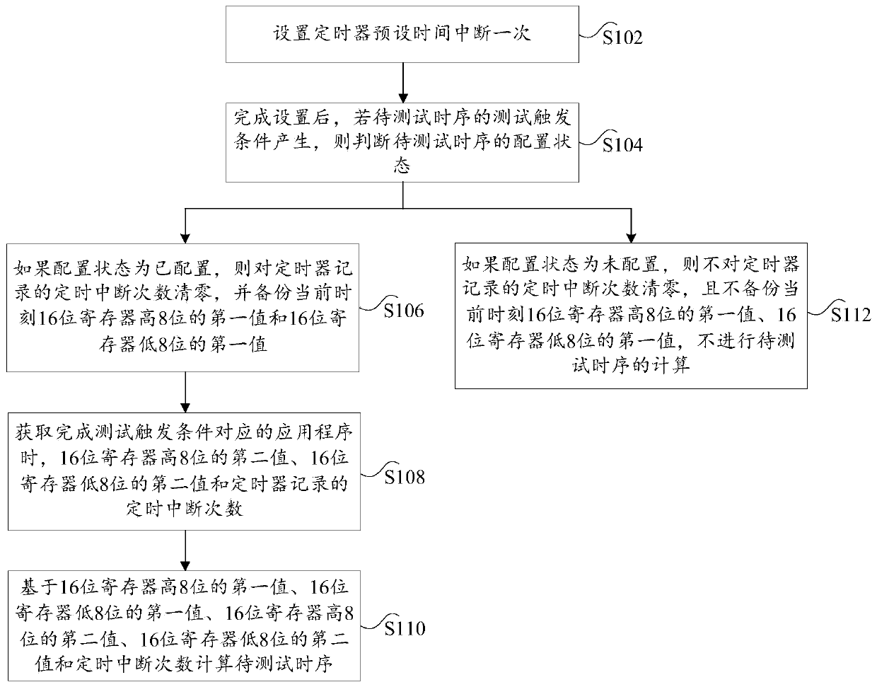
[0048] figure 1 is a flow chart of a method for timing measurement according to an embodiment of the present invention, the method is applied to a micro control unit, such as figure 1 As shown, the method includes the following steps:

[0049] Step S102, setting the timer preset time to interrupt once;

[0050] In the embodiment of the present invention, the MCU system clock is 72M, and the 48-fold frequency division is given to the timer. The timer is 16 bits and is in an up-counting mode. Once the timer is ena...

Embodiment 2

[0081] The embodiment of the present invention also provides a timing measurement device. The timing measurement device is applied to a micro control unit and is mainly used to implement the timing measurement method provided in the above content of the embodiment of the present invention. The following provides the embodiment of the present invention The timing measurement device is introduced in detail.

[0082] Figure 4 is a schematic diagram of a timing measurement device according to an embodiment of the present invention, such as Figure 4 As shown, the device for timing measurement mainly includes a setting module 10, a judgment module 20, a backup module 30, an acquisition module 40 and a calculation module 50, wherein:

[0083] The setting module is used to set the timer preset time to interrupt once;

[0084] The judgment module is used for judging the configuration state of the sequence to be tested if the test trigger condition of the sequence to be tested is ge...


PUM


Abstract

The invention provides a time sequence measurement method and device. The time sequence measurement method comprises the following steps: setting a timer to be interrupted once at preset time; if thetest triggering condition of the to-be-tested time sequence is generated, judging the configuration state of the to-be-tested time sequence; if the to-be-tested time sequence is configured, resettingthe interrupt flag of the timer, resetting the timing interrupt times recorded by the timer, and backing up a first value of a 16-bit register with 8 higher bits and a first value of a 16-bit registerwith 8 lower bits at the current moment; when the application program corresponding to the test triggering condition is completed, obtaining a second value of the 16-bit register with 8 higher bits,a second value of the 16-bit register with 8 lower bits and the timing interruption times recorded by the timer; and calculating the to-be-tested time sequence based on the values. The purpose of automatically measuring the to-be-tested time sequence can be achieved through software, operation is easy, and the testing efficiency is high.

Description

technical field [0001] The present invention relates to the technical field of measurement, in particular to a method and device for timing measurement. Background technique [0002] In the MSA protocol (multi-source agreement, multi-source agreement) applicable to optical module products, many timing requirements are defined. For example, the assert time (declared time) and deassert time (declared time) of the TX_DISABLE and RX_LOS signals are defined in the SFF-8472 protocol ( Release time), the assert time of the TX_FAULT signal (declaration time). In addition, the SFF_8431 protocol also defines the storage time (Twr) of SFP+ memory information, and the modules shipped must meet these requirements. [0003] At present, the measurement of these timings is mainly by giving the trigger conditions, and then configuring the test pins to output different levels through the firmware, soldering the leads to connect the test pins to the oscilloscope probes, or connecting the test...

Claims


Application Information

Patent Timeline
Patent Type & Authority Applications(China)
IPC IPC(8): G06F11/22
CPCG06F11/2231Y02D10/00
Inventor 黄安珠谢怀堂王艳红
Owner DONGGUAN MENTECH OPTICAL & MAGNETIC CO LTD
Why Eureka
Try Eureka