
Test device for current sensor

A current sensor and testing device technology, which is applied in the direction of measuring devices, measuring device casings, and parts of electrical measuring instruments, can solve the problems of low testing efficiency of testing devices

Inactive Publication Date: 2019-11-22
WASION GROUP HLDG
View PDF9 Cites 0 Cited by
  • Summary
  • Abstract
  • Description
  • Claims
  • Application Information

AI Technical Summary

Problems solved by technology

[0004] The main purpose of the present invention is to provide a test device for current sensors, aiming to solve the technical problem of low testing efficiency of test devices for current sensors in the prior art

Method used


Image

  • Test device for current sensor
  • Test device for current sensor
  • Test device for current sensor

Examples


Embodiment Construction

[0028] The following will clearly and completely describe the technical solutions in the embodiments of the present invention in conjunction with the accompanying drawings in the embodiments of the present invention. Obviously, the described embodiments are only part of the embodiments of the present invention, not all of them. Based on the implementation manners in the present invention, all other implementation manners obtained by persons of ordinary skill in the art without creative efforts fall within the protection scope of the present invention.

[0029] It should be noted that all directional indications (such as up, down, etc.) in the embodiments of the present invention are only used to explain the relative positional relationship, movement conditions, etc. between the components in a certain posture (as shown in the drawings), If the specific posture changes, the directional indication also changes accordingly.

[0030] In addition, in the present invention, descript...


PUM


Abstract

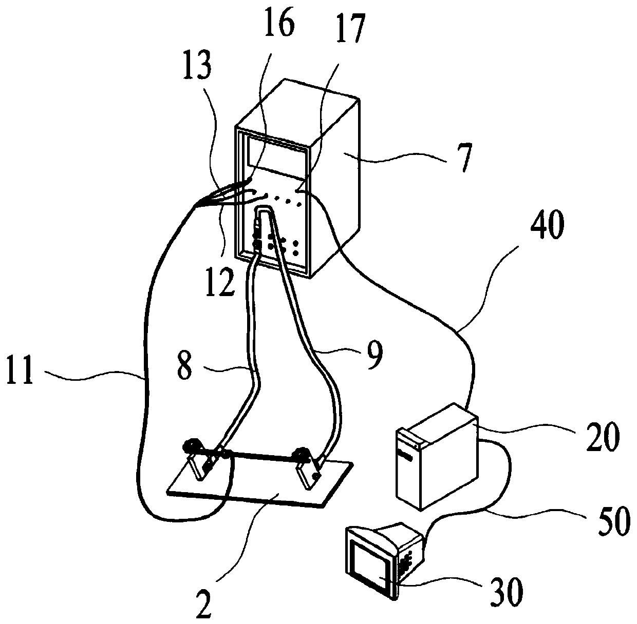
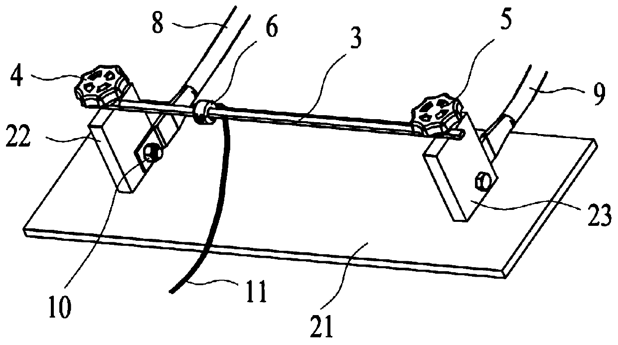
The invention provides a test device for a current sensor. The test device for the current sensor comprises a mounting rack and a control box. The mounting rack comprises a bottom plate, a left support, a right support, a copper bar connecting the left support and the right support, and a left adjustment handle and a right adjustment handle which are arranged on the copper bar, wherein the left support and the right support are mounted on the bottom plate; the left adjustment handle and the right adjustment handle are used for tightening or loosening the copper bar; and multiple current sensors can be mounted on the copper bar. The control box comprises a voltage test module, a power supply module and a current source module, wherein the power supply module is connected with the current sensors and is used for providing power to the current sensors; the current source module is connected with the left support and the right support and is used for powering on the copper bar to provide aprimary side bus current to the current sensors; and the voltage test module is connected to the sensors and is used for measuring output voltage of the current sensors. The test device has the advantages of high test efficiency.

Description

technical field [0001] The invention relates to the field of testing devices, in particular to a testing device for a current sensor. Background technique [0002] Current sensors are widely used in various fields such as industry, automobiles, transportation, and new energy. Current sensors are divided into open-loop and closed-loop structures. With the advancement of science and technology, the continuous improvement and development of high-speed rail technology, the successful research and development of high-end smart meters, and the continuous advancement of intelligent manufacturing, the requirements for the accuracy and performance of sensors are constantly improving, so the requirements for the performance and efficiency of corresponding test devices are also increasing. come higher. The traditional test method is to use a copper rod as the primary terminal of the current sensor to provide the current sensor with the bus current of the primary side. The wrench is l...

Claims


Application Information

Patent Timeline
IPC IPC(8): G01R35/00G01R1/04
CPCG01R1/0408G01R35/00
Inventor 刘硕邹强任智仁周宣周为
Owner WASION GROUP HLDG
Learn More