
Sample stretching device for in-situ infrared spectroscopic analysis

An infrared spectrum analysis and stretching device technology, which is applied in the field of sample stretching devices, can solve the problems of cumbersome operation, repeated replacement of biaxially stretched films, and low efficiency, and achieve the effects of simplifying the detection process, easy implementation, and improving work efficiency

Active Publication Date: 2019-11-22
GUANGDONG UNIV OF TECH
View PDF3 Cites 0 Cited by
  • Summary
  • Abstract
  • Description
  • Claims
  • Application Information

AI Technical Summary

Problems solved by technology

[0004] The present invention provides a sample stretching device for in-situ infrared spectrum analysis in order to solve the problems of repeated sample replacement, cumbersome operation and low efficiency in the testing process of existing equipment for biaxially stretched films

Method used


Image

  • Sample stretching device for in-situ infrared spectroscopic analysis
  • Sample stretching device for in-situ infrared spectroscopic analysis
  • Sample stretching device for in-situ infrared spectroscopic analysis

Examples


Embodiment 1

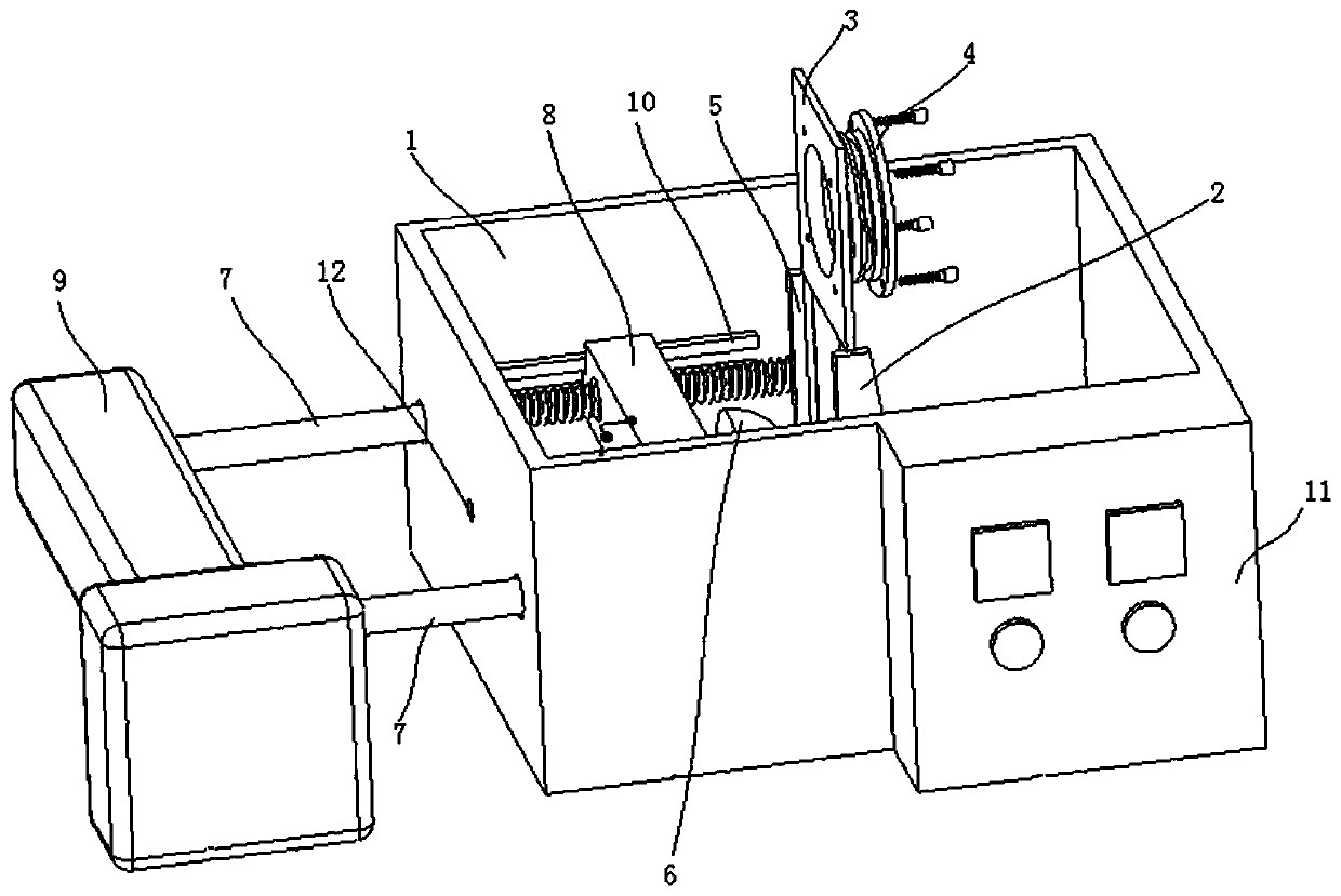
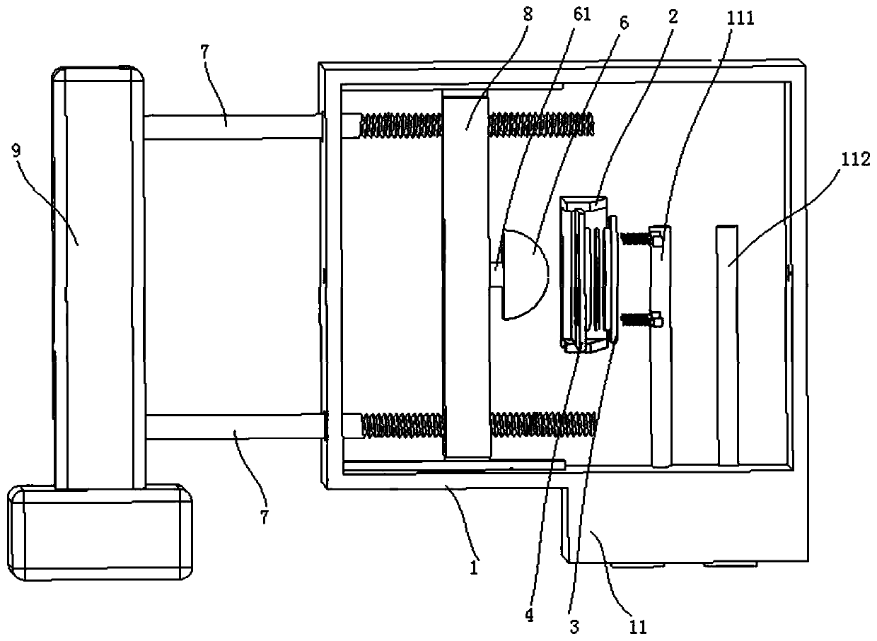
[0030] A sample stretching device for in situ infrared spectroscopic analysis, such as Figure 1~4 As shown, it includes: a housing 1, the housing 1 is provided with a cavity, and the housing 1 is also provided with a sample placement module, an extrusion module, and a temperature control module 11;

[0031] The housing 1 is provided with a first through hole 12 penetrating through the housing 1; in this embodiment 1, there are two first through holes 12, which are arranged on the front and rear sides of the housing 1 respectively. When performing infrared spectrum analysis, the infrared light emitted by the infrared spectrum analyzer can be irradiated to the sample to be tested through the first through hole 12 on the front side of the housing 1 and transmitted through the first through hole 12 on the rear side of the housing 1 go out;

[0032] The sample placement module is used to install and fix the sample to be tested inside the housing 1, and the sample is installed and...

Embodiment 2

[0038] In this embodiment 2, the sample stretching device provided in the above embodiment 1 is applied to an in-situ infrared spectrum analysis system, the system includes an infrared spectrum analyzer, and the sample placement module on the housing 1 and the hollow compact 6 are set In the sample chamber of the infrared spectrum analyzer, other components of the sample stretching device are arranged outside the sample chamber of the infrared spectrum analyzer.

[0039] When testing, such as Figure 6 As shown, the light emitted by the infrared light source in the spectrum analyzer is collected and reflected by the elliptical mirror, and the reflected light reaches the collimating mirror after passing through the grating, and the parallel reflected light reflected from the collimating mirror is directed to the interferometer (in this embodiment 2 The interferometer includes a beam splitter, a fixed mirror and a moving mirror), the parallel interference light from the interfer...


PUM


Abstract

The invention discloses a sample stretching device for in-situ infrared spectroscopic analysis. The sample stretching device comprises a shell, a cavity is arranged in the shell, and a sample placingmodule and an extrusion module are also arranged on the shell; a first through hole penetrating the shell is formed in the shell; the sample placing module is used for mounting and fixing a to-be-tested sample in the shell, and the sample directly faces the first through hole of the shell after being mounted and fixed; and the extrusion module is used for extruding the sample mounted and fixed onthe sample placement module. The device provided by the invention can achieve bidirectional stretching simulation of a sample film and in-situ infrared measurement at the same time, does not need to repeatedly take down a sample from extrusion equipment and then install the sample, simplifies the detection process of obtaining spectral data, and improves the working efficiency of sample detection.The device is simple in structure and easy to implement.

Description

technical field [0001] The invention relates to the technical field of infrared spectrum analysis, in particular to a sample stretching device for in-situ infrared spectrum analysis. Background technique [0002] According to different manufacturing processes, the preparation of films is divided into uniaxial stretching and biaxial stretching. Among them, the mechanical properties of uniaxially stretched films in the vertical stretching direction will be relatively poor. Thin neck phenomenon, the film exhibits anisotropy. The biaxially stretched film has average performance in all directions, that is, isotropy. The infrared spectroscopic analysis instrument can test the characteristic groups in the sample, and then determine the structure and type of the film sample. [0003] However, in order to obtain the dynamic change process of the sample under different stretching degrees, the current testing equipment needs to perform a series of stretching on the film sample on the...

Claims


Application Information

Patent Timeline
IPC IPC(8): G01N21/3563G01N21/01G01N3/08
CPCG01N21/3563G01N21/01G01N3/08G01N2021/3572
Inventor 袁子丹雷彩红徐睿杰
Owner GUANGDONG UNIV OF TECH
Learn More