
Array cylindrical group type multi-stage lamination micro-channel throttling heat exchange refrigerator

A column group and micro-channel technology, applied in refrigerators, refrigeration and liquefaction, lighting and heating equipment, etc., can solve the problems of small air intake, low heat exchange efficiency, and limited space for cooling temperature drop

Active Publication Date: 2019-11-22
UNIV OF SHANGHAI FOR SCI & TECH
View PDF6 Cites 0 Cited by
  • Summary
  • Abstract
  • Description
  • Claims
  • Application Information

AI Technical Summary

Problems solved by technology

However, the above-mentioned throttling refrigerator has low pressure bearing capacity, the inflow gas pressure is limited by the silicon material, and there is limited space for the cooling temperature to drop. At the same time, its structure cannot be stacked in multiple layers, resulting in a small air intake and low cooling capacity.
In addition, the existing micro-channel refrigerator is a single-stage heat recovery, throttling refrigeration, using a refrigerant, the final cooling temperature is limited
[0004] In summary, the existing micro-channel throttling refrigerators have small air intake, low heat transfer efficiency, and limited cold-end temperature, which restricts the application and development of micro-channel throttling refrigerators.

Method used


Image

  • Array cylindrical group type multi-stage lamination micro-channel throttling heat exchange refrigerator
  • Array cylindrical group type multi-stage lamination micro-channel throttling heat exchange refrigerator
  • Array cylindrical group type multi-stage lamination micro-channel throttling heat exchange refrigerator

Examples


Embodiment 1

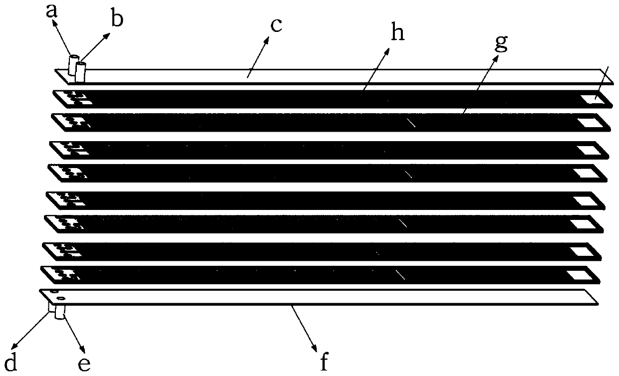
[0033] Such as figure 1 , 2 As shown, the array cylinder group multi-stage laminated microchannel throttling heat exchange refrigerator includes an upper cover plate c stacked in sequence, a plurality of upper plates h and a plurality of lower plates g stacked up and down staggered, and a lower cover Plate f, high-pressure gas inlet pipe a, low-pressure gas outlet pipe b, high-pressure gas outlet pipe d, and low-pressure gas inlet pipe e.

[0034] The upper and lower upper cover plates c and lower cover plates f with a certain thickness play a role in supporting and stabilizing the entire refrigerator.

[0035] The upper cover plate c is respectively provided with through high-pressure gas inlet holes and low-pressure gas outlet holes.

[0036] The upper plate h is rectangular, including the inlet and outlet sections, the channel section and the evaporation chamber hi.

[0037] Such as image 3 As shown, the inlet and outlet section has a high-pressure inlet hole ha, a hig...

Embodiment 2

[0085] Such as Figure 11 , Figure 12As shown, the other structure of this embodiment is the same as that of Embodiment 1, except that the flow channel h1, flow channel h3, flow channel h4, flow channel g3, and flow channel g6 in embodiment 1 are changed from S-shaped channels to straight rectangular channels. , the rectangular channel is a concave rectangular groove set on the plate, and the raised cylindrical needle rib set in the flow channel is cancelled.

[0086] When the gas passes through the flow channel h1, it will be accompanied by the Bernoulli effect and the burnt soup effect, and the Bernoulli effect is dominant at this stage, and the connection between the flow channel h1 and the flow channel h3 adopts the form shown in h8' , the high-pressure gas produces a large pressure drop here after passing through the h1 channel, forming the first throttling and cooling, and at the same time, it can be pre-cooled by the low-pressure gas after throttling by the lower plat...

Embodiment 3

[0088] Such as Figure 13 , Figure 14 As shown, the other structure of this embodiment is the same as that of Embodiment 1, except that the flow channel h1, flow channel h3, flow channel h4, flow channel g3, and flow channel g6 in Example 1 are changed from S-shaped channels to be set in channels A plurality of columns arranged in forked rows are used for throttling and support.

[0089] Function and effect of embodiment

[0090] The structural innovation of the array cylinder group type multi-stage stacked microchannel throttling heat exchange refrigerator in this embodiment is to completely isolate the high and low pressure gas from entering the refrigerator to recovering the gas, which is suitable for the mixing of high and low pressure gases Afterwards, they will influence each other on their respective properties or reaction situations; secondly, the two kinds of gases in this structure are throttled and cooled twice. The flow can generate more cold energy into the ev...


PUM


Abstract

The invention discloses an array cylindrical group type multi-stage lamination micro-channel throttling heat exchange refrigerator. The refrigerator comprises an upper cover plate, multiple upper sheets, multiple lower sheets, and a lower cover plate, wherein the upper cover plate, the upper sheets, the lower sheets and the lower cover plate are overlapped in sequence; each upper sheet comprises achannel segment, and each channel segment comprises a first runner, a second runner, a third runner and a fourth runner; the first runners, the second runners, the third runners and the fourth runners are provided with inwards-concave S channels arranged in the length direction of the channel segments, multiple protruding cylindrical needle ribs are arranged in the first runners, the third runners and the fourth runners, the density of the cylindrical needle ribs in the fourth runners is larger than that of the cylindrical needle ribs in the third runners, the density of the cylindrical needle ribs in the third runners is larger than that of the cylindrical needle ribs in the first runners, the first runners are adjacent to the second runners, lengths, along the channel segments, of the first runners and lengths, along the channel segments, of the second runners are same, one ends of the third runners are in communication with the first runners, the other ends of the third runners communicate with the fourth runners, one ends of the fourth runners communicate with the third runners, and the other ends of the fourth runners communicate with evaporation cavities.

Description

technical field [0001] The invention belongs to the field of enhanced heat exchange throttling refrigeration, and in particular relates to an array column group type multi-stage laminated microchannel throttling heat exchange refrigerator formed by microchannel two-stage throttling precooling. Background technique [0002] Miniature throttling refrigerators use the Joule-Thomson effect (J-T effect) for refrigeration, and are widely used in occasions with small size and space, such as inner cavity cryotherapy, infrared night vision devices, etc. At present, the main J-T effect refrigerator still adopts the Hampson type (spiral finned tube type), the stainless steel tube with an outer diameter of 0.5mm-1mm is wound around the mandrel, and the high-pressure gas flows through the entire stainless steel tube and enters the capillary throttling of the tube head. . The throttled low-pressure gas flows back and skims the outer fins of the stainless steel tube to pre-cool the incomi...

Claims


Application Information

Patent Timeline
IPC IPC(8): F25B9/02
CPCF25B9/02
Inventor 崔晓钰耿晖王鹏佘海龙
Owner UNIV OF SHANGHAI FOR SCI & TECH
Learn More