Impeller fastener, conveying device and supercharging device
A technology for conveying devices and fasteners, which is applied to parts of pumping devices for elastic fluids, supporting components of blades, pump components, etc. The effect of stripping and increasing the fastening strength
- Summary
- Abstract
- Description
- Claims
- Application Information
AI Technical Summary
Problems solved by technology
Method used
Image
Examples
no. 1 example
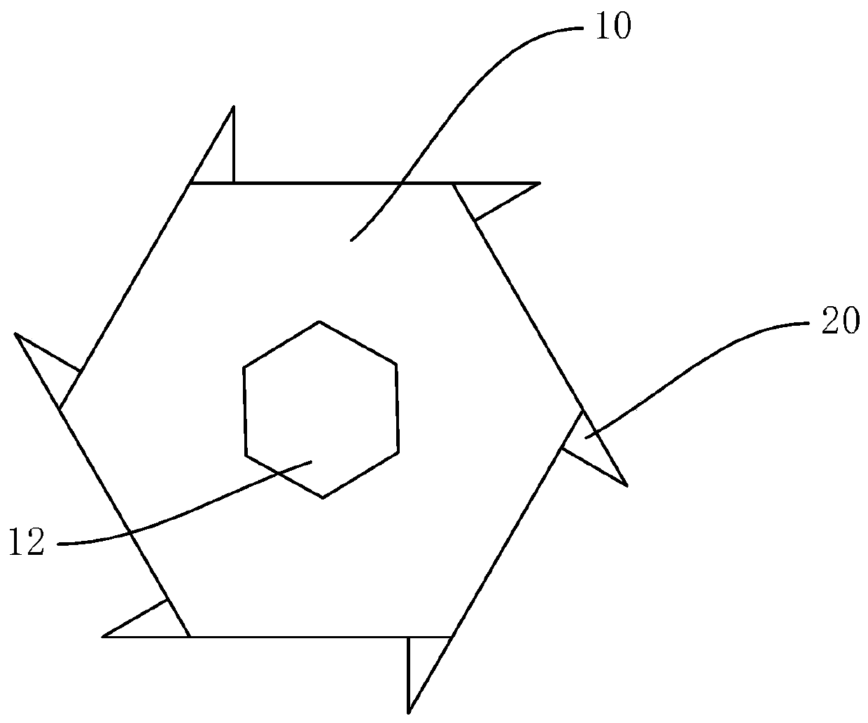
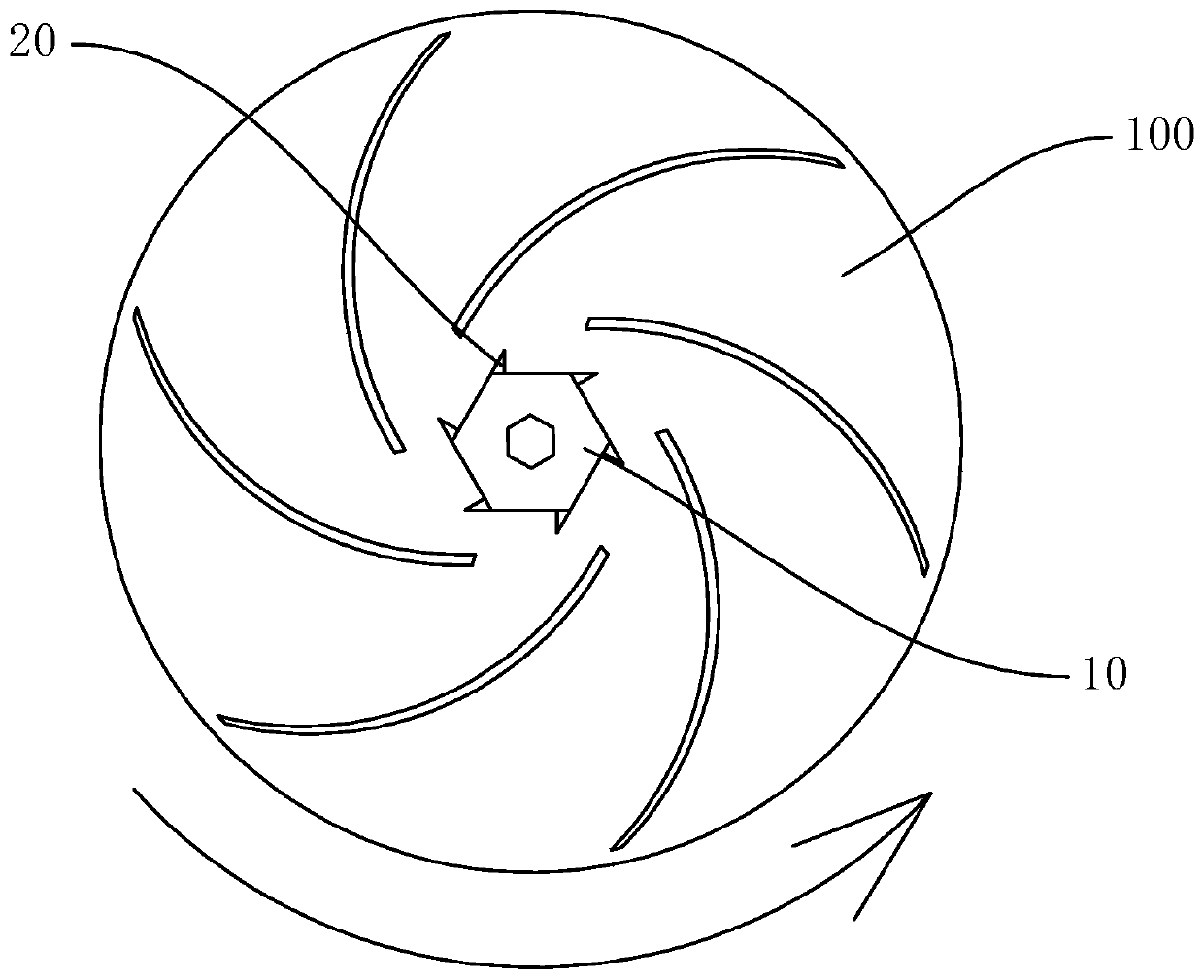
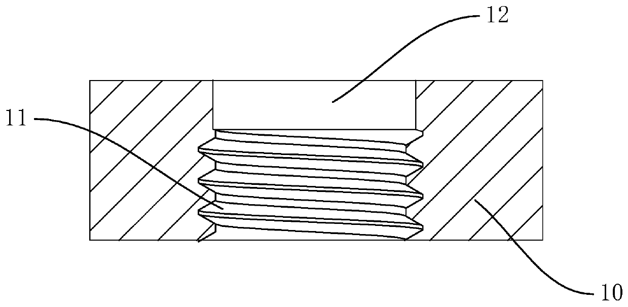
[0027] refer to Figure 1 to Figure 3 , the impeller fastener in this embodiment includes a fastening body 10, based on the edge of the fastening body 10 extending a number of lugs 20, the fastening body 10 is used to fix the impeller 100, the fastening body 10 can be fixed to the impeller At the end face of the impeller 100 , the fastening body 10 and the impeller 100 are relatively fixed, and the fastening body 10 can rotate synchronously with the rotation of the impeller 100 . When the impeller 100 rotates, it can drive the fluid around it to move along the direction of rotation of the impeller 100. Because the extension direction of the lug 20 and the fastening direction of the fastening body 10 to the impeller 100 are opposite to the direction of rotation of the impeller 100, the fluid moves in the same direction as the impeller 100. The lugs 20 contact and apply a force to the lugs 20 opposite to the rotation direction of the impeller 100, so that the rotation trend of t...
no. 2 example
[0037] refer to Figure 4 The difference between this embodiment and the first embodiment is that the lug 20 in this embodiment is configured as a piece, and the piece extends outward based on the side of the fastening body 10 , which further simplifies the structure of the lug 20 . In this embodiment, there are three lugs 20 , which are evenly distributed along the edge of the fastening body 10 , extend based on the side of the fastening body 10 , and are flush with the side of the fastening body 10 . Of course, the number of lugs 20 can be appropriately increased. For example, each side of the fastening body 10 is connected with lugs 20; A certain angle, such as being perpendicular to the side of the fastening body 10 , increases the strength of the force applied by the fluid to the lug 20 .
[0038] The sheet body is set as a rigid structure to ensure the effectiveness of motion transmission between the fastening body 10 and the lug 20, so that the resistance exerted by th...
no. 3 example
[0041] refer to Figure 6The difference between this embodiment and the first embodiment is that the section of the fastening body 10 is set as a circle, and the lugs 20 are evenly distributed and extend outward based on the edge of the fastening body 10, so as to ensure that the lugs 20 can receive the applied fluid. force. And because the fastening body 10 is circular, the processing is more convenient, and the production efficiency of the impeller fastening device is improved.
[0042] The present invention also provides a conveying device, which includes the above-mentioned impeller fastener, and also includes an impeller 100 and a rotating shaft for driving the impeller 100 to rotate, the impeller fastener is fixed on the end of the impeller 100, and the rotating shaft drives the impeller 100 rotates, so that the impeller fasteners rotate synchronously with the impeller 100. The impeller 100 realizes the delivery of fluid during the rotation process, and the fluid exerts...
PUM
 Abstract
Description
Claims
Application Information
 - R&D
- Intellectual Property
- Life Sciences
- Materials
- Tech Scout
- Unparalleled Data Quality
- Higher Quality Content
- 60% Fewer Hallucinations
Browse by: Latest US Patents, China's latest patents, Technical Efficacy Thesaurus, Application Domain, Technology Topic, Popular Technical Reports.
© 2025 PatSnap. All rights reserved.Legal|Privacy policy|Modern Slavery Act Transparency Statement|Sitemap|About US| Contact US: help@patsnap.com


