
Start-generation system power converter and control method thereof

A technology for power converters and power generation systems, applied in the direction of output power conversion devices, control systems, control generators, etc., can solve problems such as limiting SGCU efficiency and power density, achieve better and more flexible control strategies, improve system efficiency, Effect of reducing conduction loss

Active Publication Date: 2019-11-19
南京兴航动力科技有限公司 +1
View PDF4 Cites 6 Cited by
  • Summary
  • Abstract
  • Description
  • Claims
  • Application Information

AI Technical Summary

Problems solved by technology

The heat loss caused by the voltage drop of the three-phase rectifier bridge diode in the main power circuit will multiply as the power increases, which greatly limits the efficiency and power density of the SGCU

Method used


Image

  • Start-generation system power converter and control method thereof
  • Start-generation system power converter and control method thereof
  • Start-generation system power converter and control method thereof

Examples


Embodiment Construction

[0026] The technical solution of this patent will be described in detail below in conjunction with the accompanying drawings, taking a three-phase motor system as an example.

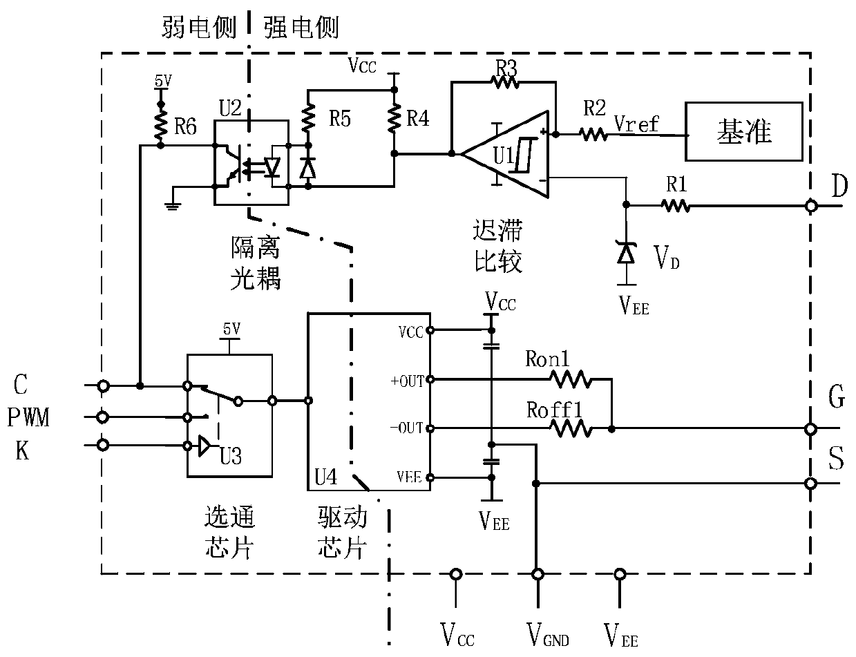
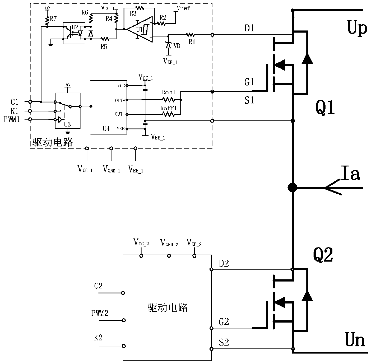
[0027] Such as figure 1Provides a general block diagram of the power converter used in the aviation starting power generation system, as shown in the figure, including MOSFET three-phase full bridge, drive circuit, isolated drive power supply, control circuit (arranged on the digital control circuit board as shown in the figure) and current sampling circuit. Each MOSFET in the three-phase full bridge has an independent drive circuit, and the drive circuits and the control circuit are respectively connected by PWM signal, K signal and C signal. The PWM signal is the switch signal sent by the control circuit to the drive circuit. The K signal is the strobe signal sent by the control circuit to the drive circuit, and the C signal is the MOSFET state signal sent by the drive circuit to the control circuit,...


PUM


Abstract

The invention discloses a start-generation system power converter and a control method thereof. The power converter includes a three-phase full-bridge inverter module, driving circuits and a control circuit. The three-phase full-bridge inverter module consists of a MOSFET module with parasitic anti-parallel diodes. Each MOSFET corresponds to one driving circuit. The driving circuit is a compositedriving circuit. In a start mode, the driving circuit operates in a typical MOSFET driving mode and the MOSFET module achieves the function of an inverter bridge. In a generation mode, the driving circuit, in response to the strobe signal of the control circuit, selectively drives the turning on and the turning off of the MOSFET, and the MOSFET module realizes the function of a rectifier bridge. In the solution, one three-phase MOSFET module realizes the integration of a start power circuit and a generation power circuit. Through the MOSFET switching control, the on-state loss of the rectifiedoutput in the generation mode is greatly reduced and the system efficiency is improved. The power converter is easy to control and high in reliability, especially suitable for aviation low-voltage high-power starting power generation system.

Description

technical field [0001] The invention relates to a starting power generation control system, in particular to a high power density high-speed motor DC starting power main power system for an aircraft or an automobile and a corresponding control method, belonging to the technical field of starting power generation. Background technique [0002] In the current DC power supply systems used in aircraft or automobiles, most starter generators are brushed motors. The technology of the brushed motor is mature, and the control of starting and generating power is simple. However, due to the brushes and slip rings in its structure, the brushes are easy to wear and tear, and the average failure maintenance cycle is short. Therefore, the use of power electronic switching devices to replace motor brushes to realize motor current commutation has become a popular direction in the field of motor starting and power generation. [0003] The aerospace field has extremely strict requirements on...

Claims


Application Information

Patent Timeline
Patent Type & Authority Applications(China)
IPC IPC(8): H02P9/08H02P9/30H02M1/08
CPCH02M1/08H02P9/08H02P9/30
Inventor 向子琦赵承亮魏佳丹张卓然杨善水
Owner 南京兴航动力科技有限公司
Learn More