
Ratchet wheel with protection and identification layers and manufacturing method thereof

A ratchet wheel and manufacturing method technology, applied in the field of a ratchet wheel with a protective and identification layer and its manufacturing method, can solve the problems of reduced meshing force of the ratchet wheel assembly, easy to wear, and the coating layer falls off, and achieves improved wear resistance and is not easy to fall off. Effect

Inactive Publication Date: 2019-11-19
陈怡富
View PDF11 Cites 0 Cited by
  • Summary
  • Abstract
  • Description
  • Claims
  • Application Information

AI Technical Summary

Problems solved by technology

[0005] 1. The electroplating layer only involves the change of the local surface color of the ratchet, which is decorative or recognizable. According to the current electroplating process, such a coating is easy to fall off
[0006] 2. The decorative coating cannot be fully implemented on the entire surface of the ratchet assembly of the ratchet wrench, which may lead to a decrease in the meshing force of the ratchet assembly, or the problem of the coating falling off and the teeth stuck
[0007] 3. In the ratchet tooth surface and angle groove surface of the ratchet, the two main stress-bearing parts, the previous technology has not done any surface protection treatment, and these two places are extremely prone to wear
The worn corner groove surface causes friction, obstruction and unsmoothness when the ratchet is combined with the tool head or workpiece
The worn ratchet surface will cause major problems such as jumping teeth when operating under force, or failure of the ratchet reversing function.
[0008] 4. The technology of the previous case is complicated, but its effect is only to form a color coating at both ends of the ratchet, but it hides the above-mentioned multiple problems

Method used


Image

  • Ratchet wheel with protection and identification layers and manufacturing method thereof
  • Ratchet wheel with protection and identification layers and manufacturing method thereof
  • Ratchet wheel with protection and identification layers and manufacturing method thereof

Examples


Embodiment Construction

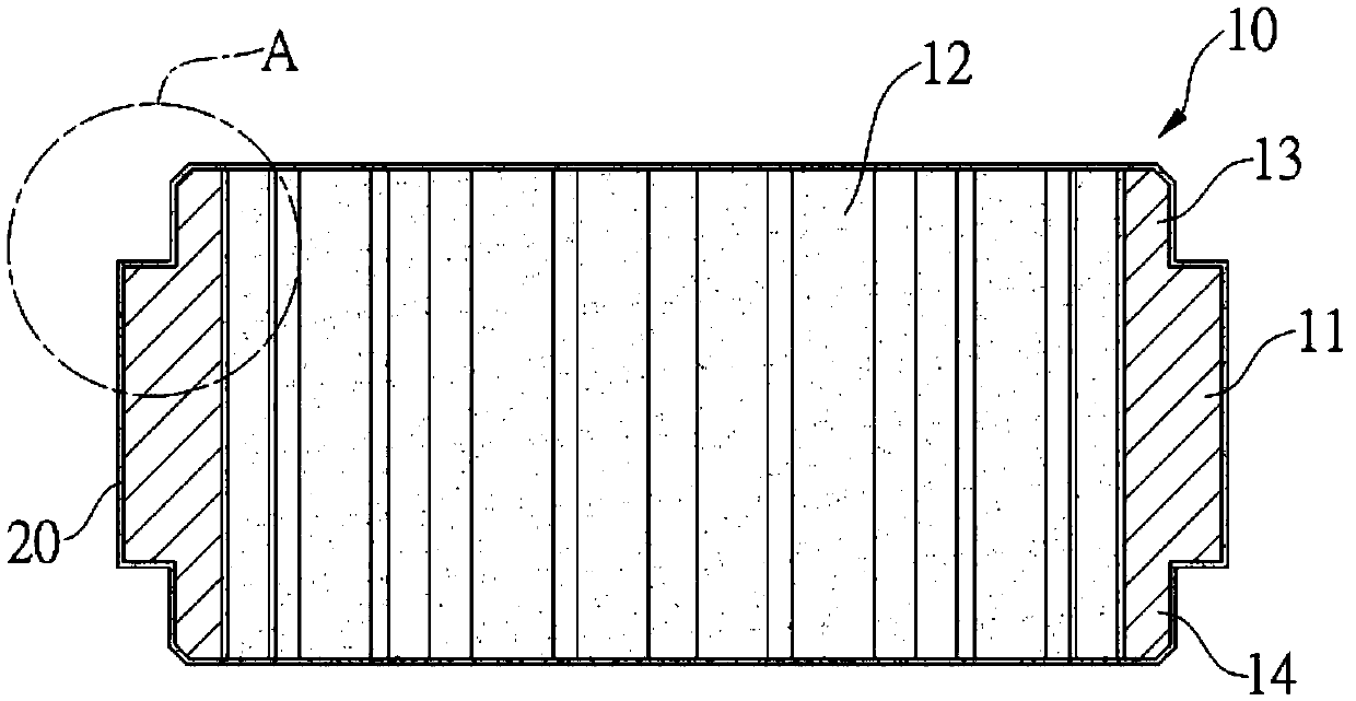
[0045] Such as figure 1 , figure 2 , Figure 5 , the ratchet manufacturing method with identification structure of the present invention, through this manufacturing method, a comprehensive protective coating 20 and a partial identification coating 40 are formed on the surface of the ratchet.

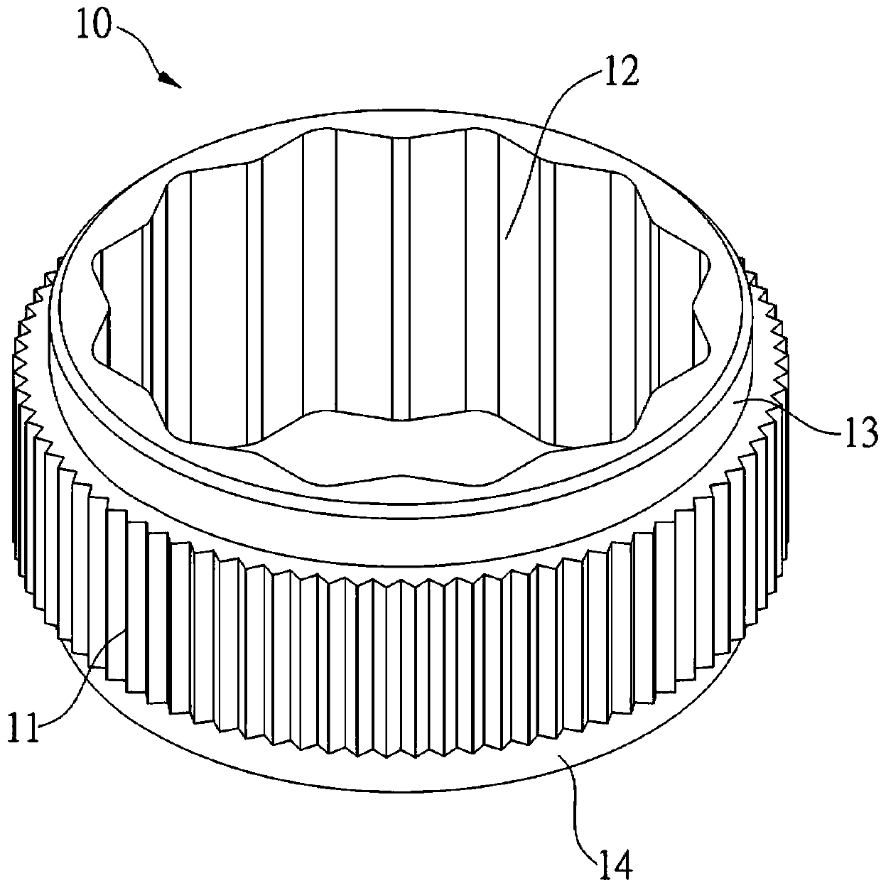
[0046] Such as figure 1 , the ratchet wheel 10 includes: an outer ring surface 11, which is a ratchet tooth surface; an inner ring surface 12, which is a polygonal fitting surface; a first end 13 and a second end 14, respectively connected to the outer ring surface 11 and the two ends of the inner ring surface 12.

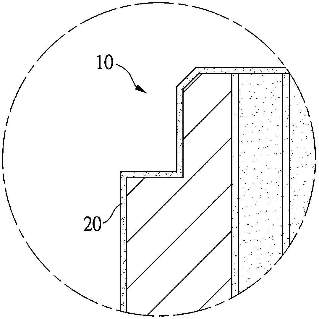
[0047] The manufacturing method includes: step 1, electroplating the above-mentioned ratchet 10 for the first time, and forming a ring on the entire surfaces of the outer ring surface 11, the inner ring face 12, the first end 13, and the second end 14 of the ratchet wheel 10. Protective coating 20 (such as figure 2 , image 3 ); Step 2, after the ratchet 10 is taken o...


PUM


Abstract

The invention provided a ratchet wheel with protection and identification layers and a manufacturing method thereof. A comprehensive protection coating and a localized identification coating can be mainly formed on the surface of the ratchet wheel by two electroplating processes. The protection coating has a high bonding force (or adhesion) with the ratchet wheel and is not prone to falling off, and the abrasion resistance, oxidation resistance and surface gloss of the ratchet wheel are improved. The identification electroplated layer plays a role for the user to visually identify the ratchetwheel, and the specification and size of the ratchet wheel or a ratchet wrench are determined by the color of the identification electroplated layer.

Description

technical field [0001] The invention relates to a method for manufacturing a protection structure and an identification structure of a ratchet wheel of a wrench. Background technique [0002] Electroplating of a specific color is made on all or part of the surface of hand tools (such as wrenches) or their components (such as sockets or ratchets), the main purpose of which is to facilitate users to quickly and accurately identify the specifications of tools or components ( Metric, Imperial), size, and can be correctly placed in the tool slot or component slot prepared by the tool box. [0003] The invention patent I424907 of Taiwan, China discloses a process technology for partially realizing a distinguishable electroplating layer on a ratchet wheel. The first way is to wrap the ratchet tooth surface of the ratchet with insulation and then electroplate it. After the electroplating is completed, the ratchet side of the ratchet does not have electroplating, while the other su...

Claims


Application Information

Patent Timeline
IPC IPC(8): C25D5/10C25D7/00C25D5/02
CPCC25D5/02C25D5/10C25D7/00
Inventor 陈怡富
Owner 陈怡富
Learn More