Sliding door for vehicle

A technology for sliding doors and car doors, which is applied to doors, vehicle parts, transportation and packaging, etc. It can solve problems such as poor consistency of internal and external water cut installation surfaces, poor glass operation stability, and water leakage of car doors, so as to improve airtightness and aesthetics. Improve the safety of side collisions and solve the effect of door water leakage

Pending Publication Date: 2019-11-19
CHINALCO MATERIALS APPL RES INST CO LTD
View PDF5 Cites 0 Cited by
  • Summary
  • Abstract
  • Description
  • Claims
  • Application Information

AI Technical Summary

Problems solved by technology

Due to the many accessories installed in the door system, it is necessary to avoid the installation and use space of the accessories in the structure. As a result, the door performance improvement space in the current market is small, and the side door collision safety is weak, especially the performance improvement of the door window frame is the most difficult.
[0003] The side impact technology and window frame performance improvement technology used in the existing automobile industry are not mature enough, the safety of side door collision is weak, and the Y-direction cavity area of ​​the anti-collision beam of the plate is small, and the sharp point of bending is prone to occur during side impact. Threat to the safety of occupants
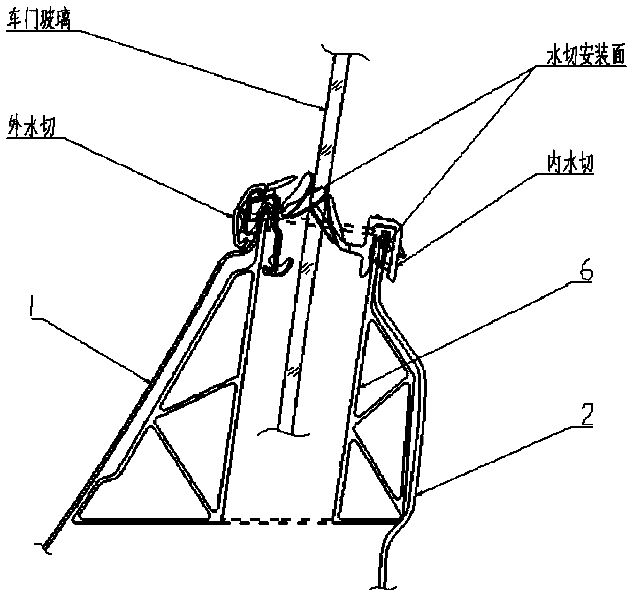
The large deformation of the window frame leads to poor running stability of the glass, and the poor consistency of the internal and external water-cut installation surfaces cannot guarantee the door sealing, resulting in frequent problems such as door leakage. However, existing researchers have not developed better side impact technology and window frame The solution of performance-enhancing technology cannot solve the current technical problems of weak side door collision safety and large window frame deformation leading to poor glass operation stability

Method used


Image

  • Sliding door for vehicle
  • Sliding door for vehicle
  • Sliding door for vehicle

Examples


Embodiment Construction

[0039] The following will clearly and completely describe the technical solutions in the embodiments of the present invention with reference to the accompanying drawings in the embodiments of the present invention. Obviously, the described embodiments are only some, not all, embodiments of the present invention. Based on the embodiments of the present invention, all other embodiments obtained by persons of ordinary skill in the art without making creative efforts belong to the protection scope of the present invention.

[0040] In the description of the present invention, unless otherwise stated, the meaning of "plurality" is two or more; the terms "upper", "lower", "left", "right", "inner", "outer" , "front end", "rear end", "head", "tail", etc. indicate the orientation or positional relationship based on the orientation or positional relationship shown in the drawings, and are only for the convenience of describing the present invention and simplifying the description, rather...


PUM


Abstract

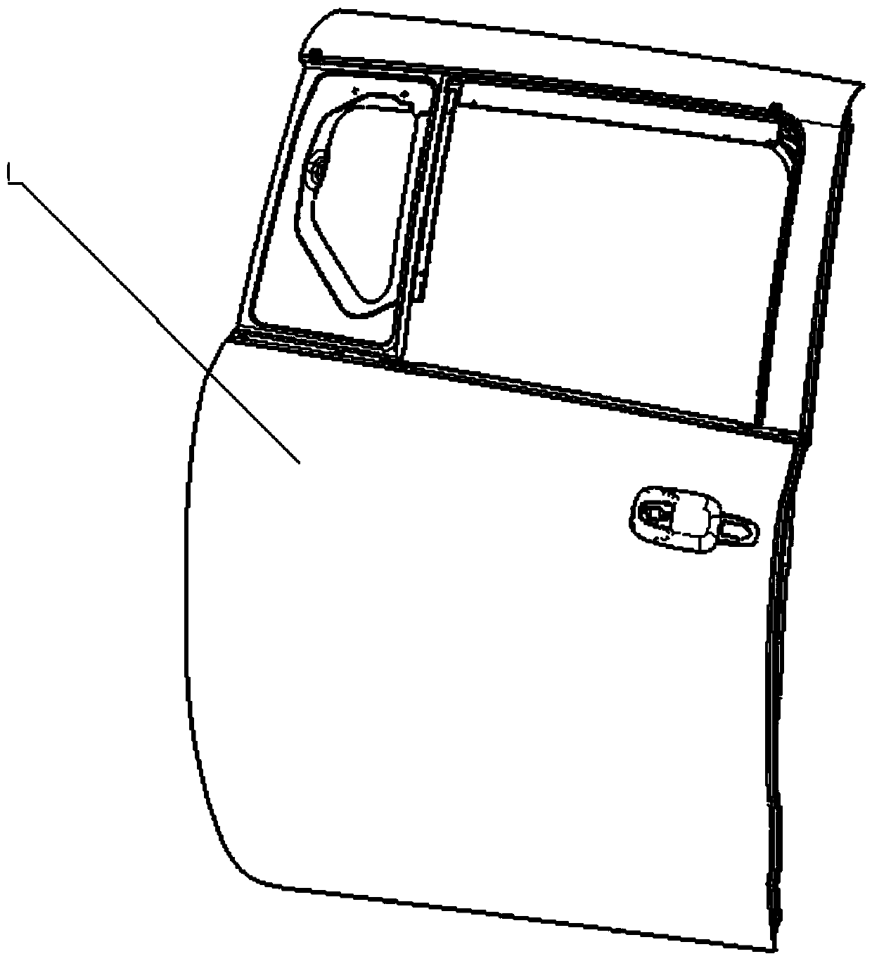
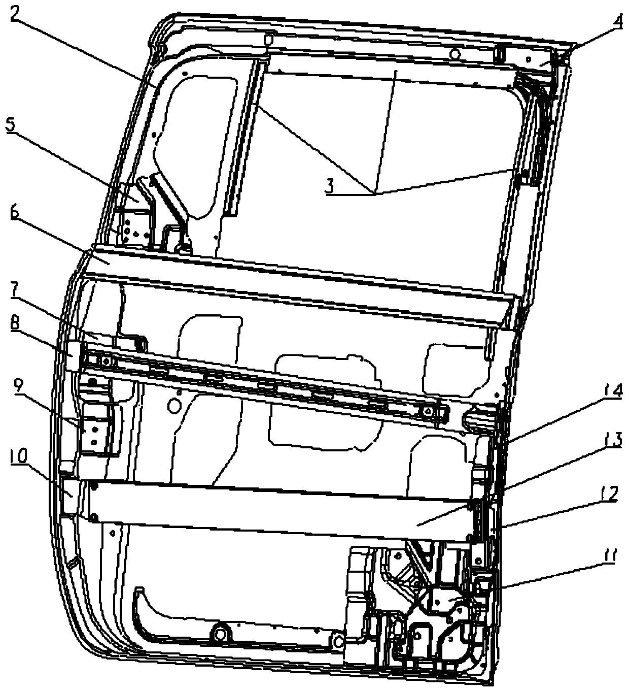
The invention relates to a sliding door for a vehicle. The sliding door comprises a vehicle door outer plate 1 and a vehicle door inner plate assembly. The vehicle door inner plate assembly comprisesa vehicle door inner plate 2 and a strip-shaped profile anti-collision beam 13. The profile anti-collision beam 13 is transversely arranged between the vehicle door inner plate 2 and the vehicle doorouter plate 1. The profile cavity section of the profile anti-collision beam 13 is of a flexible structure. The flexible structure is used for absorbing side collision energy through deformation of the flexible structure when the vehicle door collides. The sliding door for the vehicle is good in side collision energy absorbing effect, the side collision safety of the vehicle door is greatly improved, and the riding safety of people in the vehicle is guaranteed.

Description

technical field [0001] The invention relates to the technical field of automobile doors, in particular to a sliding door for automobiles. Background technique [0002] With the rapid development of the automobile industry, the door, as the most important opening and closing system in the automobile, carries functions such as safety, aesthetics, and sealing. Due to the many accessories installed in the door system, it is necessary to avoid the installation and use space of the accessories in the structure. As a result, there is little room for improving the performance of the doors on the market, and the side door collision safety is weak, especially the performance improvement of the door window frame is the most difficult. [0003] The side impact technology and window frame performance improvement technology used in the existing automobile industry are not mature enough, the safety of side door collision is weak, and the Y-direction cavity area of ​​the anti-collision beam...

Claims


Application Information

Patent Timeline
Patent Type & Authority Applications(China)
IPC IPC(8): B60J5/06
CPCB60J5/0443B60J5/0456B60J5/0483B60J5/06
Inventor 宋小雨任毅斌刘云刚徐志强胡国强
Owner CHINALCO MATERIALS APPL RES INST CO LTD
Why Eureka
Try Eureka