
Radiography apparatus and radiography method using same

A technology of radiography and equipment, which is applied in the control of radiological diagnostic equipment, instruments for radiological diagnosis, applications, etc., can solve the problems of inability to clearly show image boundaries, delay in total imaging time, image quality degradation, etc., and achieve shortening Effects of imaging time, movement speed reduction, and high resolution

Pending Publication Date: 2019-11-15
DRTECH
View PDF5 Cites 1 Cited by
  • Summary
  • Abstract
  • Description
  • Claims
  • Application Information

AI Technical Summary

Problems solved by technology

[0006] In this conventional radiography apparatus, there occurs a phenomenon of motion blur, that is, the boundary of an image acquired by the radiation detection unit cannot be clearly shown due to the movement of the radiation source, and thus the image quality is degraded
To prevent this motion blur phenomenon, a stop and shoot method is also used: the radiation source in a completely stopped state takes the projected image at an angle for imaging, and then moves the radiation source to the next position for imaging ; however, since in this method the radiation source should perform imaging in a state of complete stop, there is a problem of total imaging time delay

Method used


Image

  • Radiography apparatus and radiography method using same
  • Radiography apparatus and radiography method using same
  • Radiography apparatus and radiography method using same

Examples


Embodiment Construction

[0041] Hereinafter, embodiments of the present invention will be explained in detail with reference to the accompanying drawings. However, the present invention can be embodied in various forms, and is not limited to the embodiments described hereinafter. Rather, these embodiments are provided so that this disclosure of the invention will be complete, and will fully convey the scope of the invention to those skilled in the art. Throughout the drawings, like reference numbers refer to like elements.

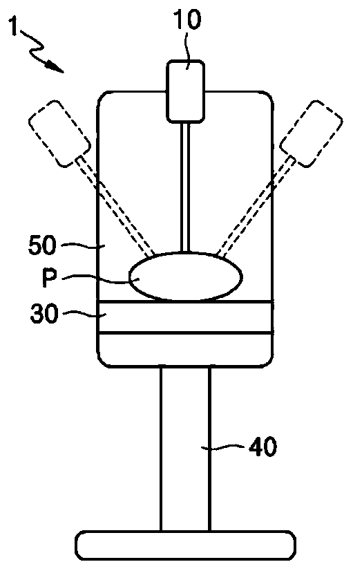
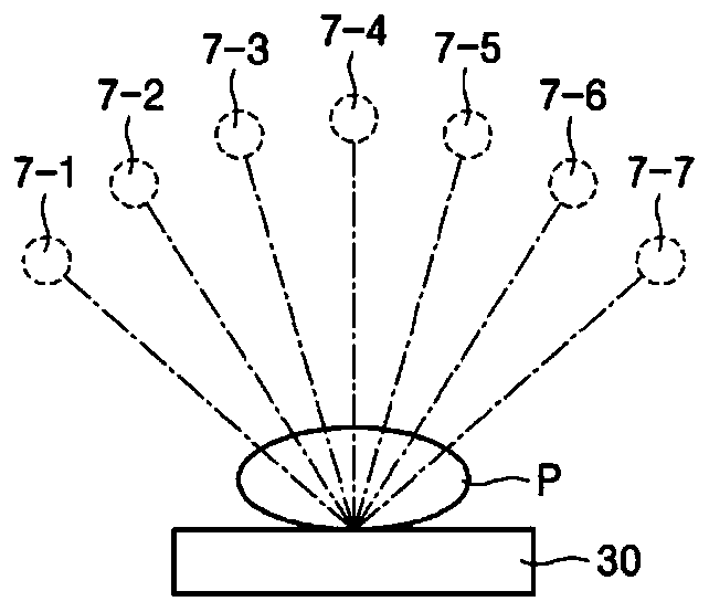
[0042] figure 1 is a drawing illustrating a digital breast tomography device, and figure 2 is a drawing illustrating an aspect of obtaining a radiation image by a radiographic apparatus.

[0043] refer to figure 1 and figure 2 , a digital breast tomosynthesis (digital breast tomosynthesis, DBT) apparatus (1) comprises: a support member (40) having a lower end portion fixed to a base plate; a main body (50) is arranged to be able to rise along the support member (40) and a ...


PUM


Abstract

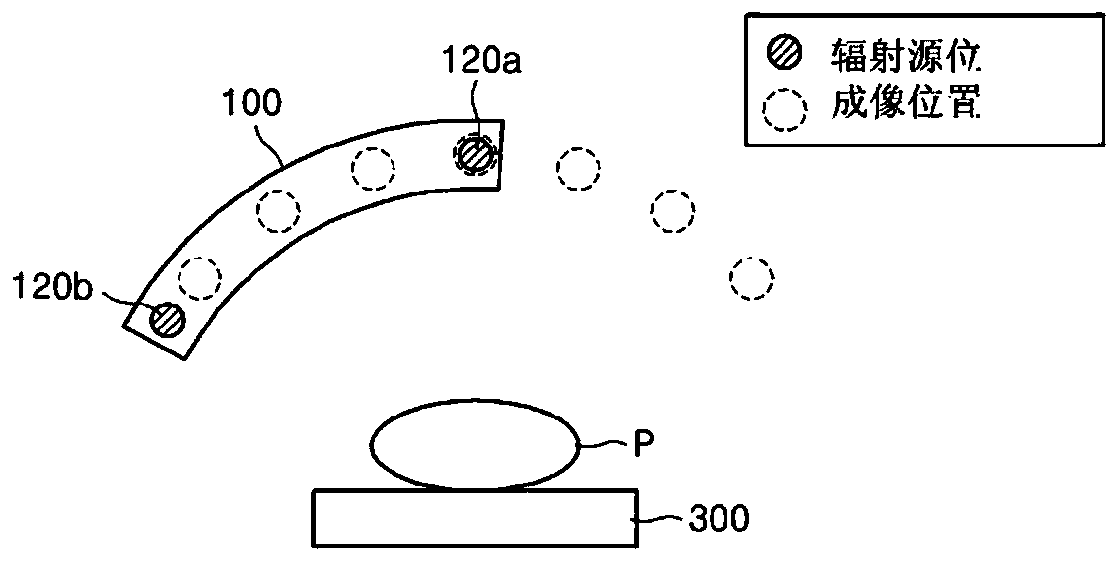
The present invention relates to a radiography apparatus and a radiography method using the same and, more particularly, to a radiography apparatus for capturing an image of an object by using radiation, and a radiography method using the same. The radiography apparatus according to an embodiment of the present invention comprises: a radiation emitting unit for emitting radiation at an object; a driving unit for moving the radiation emitting unit; a radiation detection unit for detecting radiation emitted from each of a plurality of capturing positions provided per capturing angle for the object, so as to acquire a plurality of radiation images; and a plurality of radiation sources provided in the radiation emitting unit, such that at least one thereof is arranged at one capturing positionand at least one thereof is arranged at a position spaced apart from each capturing position, according to the movement of the radiation emitting unit.

Description

technical field [0001] The present invention relates to a radiographic apparatus and a radiographic method using the same, and more particularly, to a radiographic apparatus that uses radiation to take an image of a target, and a radiographic method using the same The radiographic method of the equipment. Background technique [0002] Recently, as radiographic techniques have been applied to the semiconductor field, the radiographic techniques have rapidly developed into digital imaging techniques with advantages such as relatively high resolution, dynamic Wide area, easy to generate electrical signals and convenient data processing and storage. Digital imaging technology strongly reflects the need for early diagnosis of disease in a clinical environment that relies on the excellent diagnostic capabilities of digital images. [0003] Therefore, a digital mammography technique was introduced, which is a radiographic technique specifically for the breast, which utilizes the ...

Claims


Application Information

Patent Timeline
Patent Type & Authority Applications(China)
IPC IPC(8): A61B6/00
CPCA61B6/025A61B6/502A61B6/54A61B6/4007A61B6/4021A61B6/42
Inventor 申哲雨李在烔兪炳珉
Owner DRTECH
Learn More