
Multi-mandrel full-automatic vertical machining center

A vertical machining center, fully automatic technology, used in metal processing, metal processing equipment, metal processing machinery parts, etc., can solve the problems of waste of labor, low efficiency, inability to automatically load and unload materials, etc., to achieve the effect of saving labor

Pending Publication Date: 2019-11-15
KEDE NUMERICAL CONTROL CO LTD
View PDF6 Cites 4 Cited by
  • Summary
  • Abstract
  • Description
  • Claims
  • Application Information

AI Technical Summary

Problems solved by technology

[0003] At present, vertical machining centers with conveyor belts that can automatically load and unload materials generally have only one spindle head, and can only process one part at a time, and because they cannot automatically load and unload materials, labor is wasted and efficiency is low

Method used


Image

  • Multi-mandrel full-automatic vertical machining center
  • Multi-mandrel full-automatic vertical machining center
  • Multi-mandrel full-automatic vertical machining center

Examples


Embodiment 1

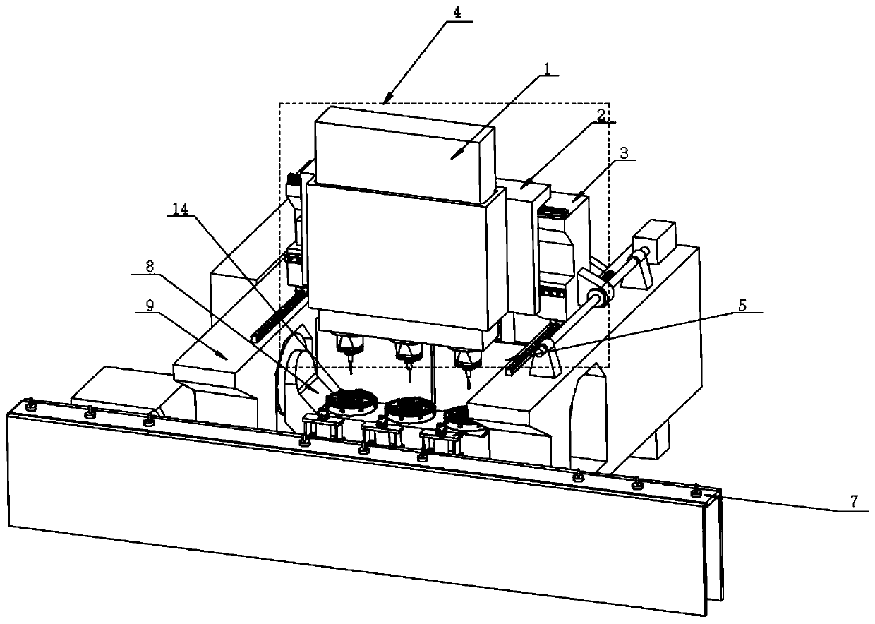
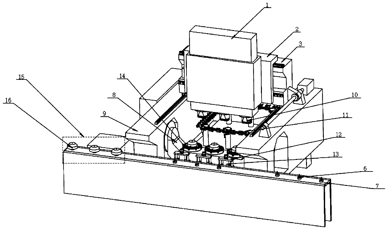
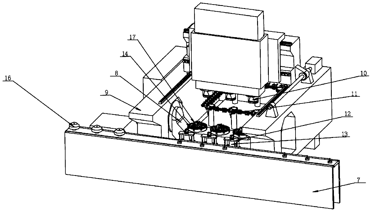
[0031] Embodiment 1: Specifically, as figure 1 As shown, the slide table 3 moves forward, that is, moves towards the direction of the conveyor belt 7, so that the ram 1 reaches the tooling area, and the control end of the machine tool automatically adjusts the position of the saddle 2, so that the main shaft of the ram 1 and the clamping tooling 12 below Keep concentricity. At this time, the position of the ram 1 is set as point A. In this embodiment, three spindle heads 10 are set. At this time, the ram 1 moves downward, driving the three spindle heads 10 to grab the clamping tool 12 below. , and rise to the specified height.

[0032] Such as figure 2 As shown, the slide table 3 continues to move forward, so that the ram 1 reaches the top of the conveyor belt 7, and a plurality of refueling areas 15 are equidistantly arranged on the conveyor belt 7, and the conveyor belt 7 runs intermittently, and the distance of each operation is the same as Adjacent to the distance betwe...

Embodiment 2

[0036] Embodiment 2: On the basis of Embodiment 1, the clamping tool can also be placed on the chain tool holder together with the tool, and the grasping of the clamping tool by the spindle head is similar to that of the clamping tool. The grabbing process of the tool is the same, and will not be repeated here.

[0037] The tool magazine door 5 in the present application is closed during the machining process, which effectively isolates the processing waste and dust outside the tool magazine area to ensure the cleanliness of the tool magazine area; one side of the actuator 4 is provided with the conveyor belt, and the other The workbench and the tool magazine area are arranged on the side, which reduces the working stroke of the spindle head and makes the whole processing process more concise and convenient.


PUM


Abstract

The invention discloses a multi-mandrel full-automatic vertical machining center. The multi-mandrel full-automatic vertical machining center comprises an executing mechanism, a lathe bed, a feeding area, a tool area, a machining area and a cutter library area, wherein the executing mechanism comprises a ram, a saddle and a sliding table; and the feeding area transversely penetrates through the lathe bed, the feeding area and the cutter library area are located on the two opposite sides of the machining area correspondingly, the feeding area is located at the forefront end of the machining center, and the executing mechanism moves above the feeding area, the tool area, the machining area and the cutter library area. According to the multi-mandrel full-automatic vertical machining center, compared with the prior art, a conveyor belt is arranged in front of a whole machine tool and transversely penetrates through the interior of the machine tool, the length of the conveyor belt can be increased and decreased according to needs, more raw materials and finished product parts can be stored by increasing the length of the conveyor belt, and labor is saved.

Description

technical field [0001] The invention relates to the technical field of machine tool processing, in particular to a multi-spindle fully automatic vertical machining center. Background technique [0002] The vertical machining center is generally composed of bed, sliding table, saddle, ram, cradle, turntable, spindle and other components. The workpiece is fixed on the turntable, and the spindle moves through the XYZ axis and the AC axis to perform complex processing on the workpiece. [0003] At present, vertical machining centers with conveyor belts that can automatically load and unload materials generally have only one spindle head, and can only process one part at a time, and because they cannot automatically load and unload materials, labor is wasted and efficiency is low. Contents of the invention [0004] The invention provides a multi-spindle fully automatic vertical machining center to overcome the above technical problems. [0005] The invention includes: executiv...

Claims


Application Information

Patent Timeline
Patent Type & Authority Applications(China)
IPC IPC(8): B23Q3/155B23Q7/02B23Q7/04B23Q7/14
CPCB23Q3/1554B23Q7/02B23Q7/04B23Q7/1405B23Q2039/006B23Q1/012B23Q3/15724B23Q3/15766B23Q11/08B23Q3/15706B23Q2230/002B23Q3/15786B23Q7/14B23Q7/045Y02P70/10B23Q1/01
Inventor 陈虎杜长林王连炀唐锐尹书强李昂宫兴林李少智
Owner KEDE NUMERICAL CONTROL CO LTD
Learn More