Method for machining stirrer shaft end part sealing ring B
A processing method and mixer technology, which are applied in the field of shaft end piece processing, can solve the problems of poor accuracy and low processing efficiency of the B ring mounting hole of the shaft end piece seal, so as to improve production efficiency, facilitate, fast and accurate processing, relative position Uniform and stable effect
- Summary
- Abstract
- Description
- Claims
- Application Information
AI Technical Summary
Problems solved by technology
Method used
Image
Examples
Embodiment 1
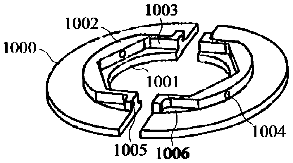
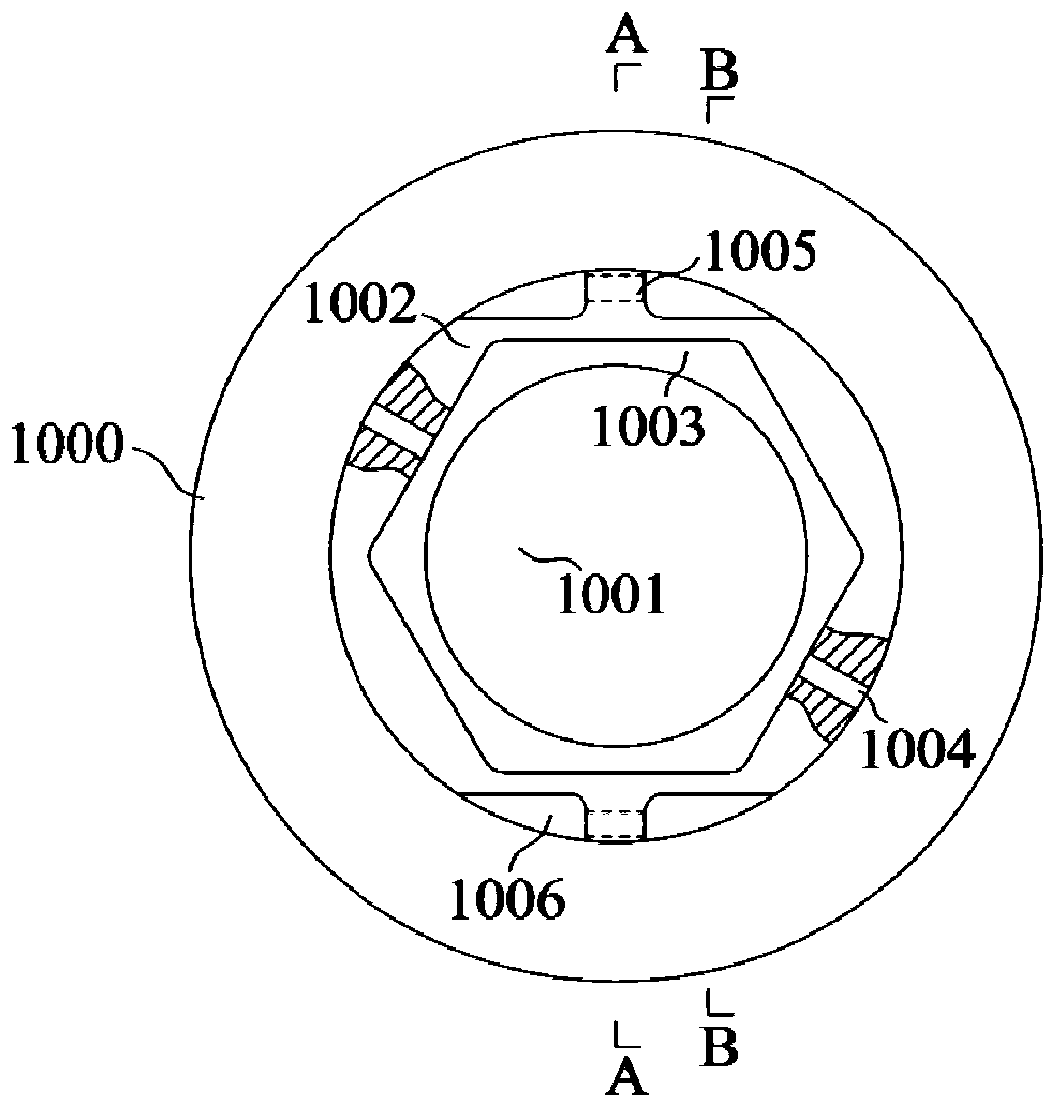
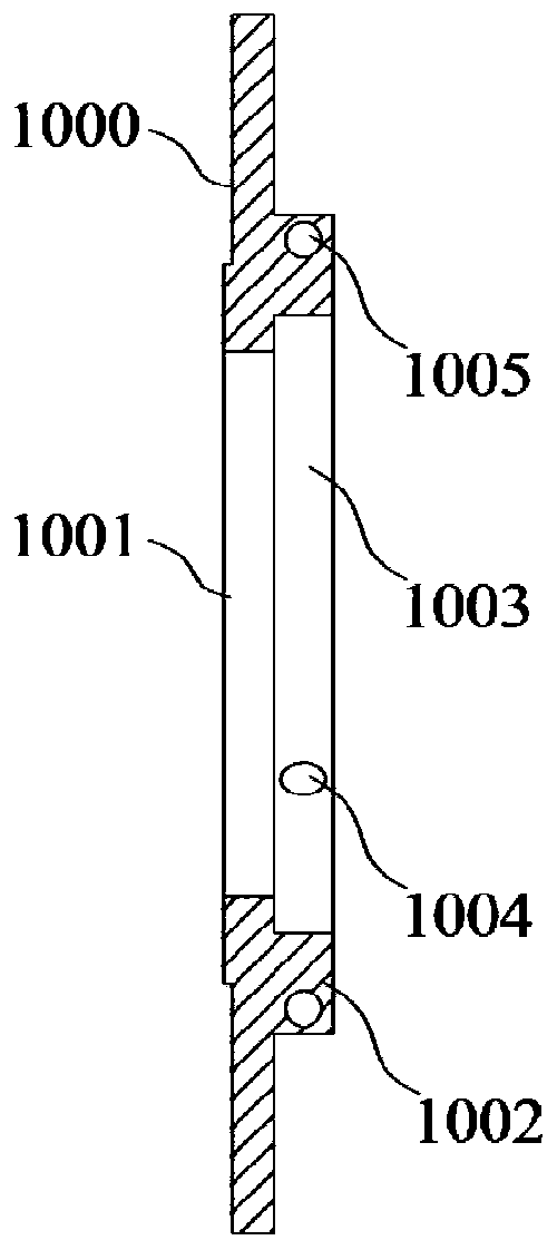
[0077] Such as figure 1 , figure 2 , image 3 and Figure 4 As shown, it is a schematic structural diagram of the seal B ring of the shaft end piece. The processing tooling of this embodiment is designed based on the installation hole 1 1004 and the installation hole 2 1005 of the shaft end piece seal B ring.
[0078] Such as Figure 5 , Figure 6 and Figure 7 As shown, the shaft end part seal B ring processing tooling installation seat 1 of the mixer shaft end part in this embodiment is an inverted T-shaped structure composed of a horizontal bottom plate 10 and a vertical vertical plate 11, wherein the vertical plate 11 is in the shape of a "convex" , the fixed block one 2 is a regular hexagonal block-shaped protrusion structure, the protrusion is arranged on the left side of the vertical plate 11, and the two sides of the fixed block one 2 are perpendicular to the horizontal plane, the positioning block one 5 and the positioning block two 6 are symmetrical It is arra...
Embodiment 2
[0084] This embodiment is modified on the basis of embodiment 1. The difference from embodiment 1 is that the fastening device of this embodiment is as Figure 12 As shown, it includes a threaded rod 8 and a knob 9. The threaded rod 8 is in the shape of a long rod, and the side wall is provided with a threaded structure. The knob 9 is in the shape of a disc. The diameter of the through hole 1001 also includes a long rod-shaped fastening rod 90 whose length is greater than the diameter of the circular through hole 1001 of the seal B ring of the shaft end piece. When assembling, the fastening rod 90 is placed between the knob 9 and the shaft end to be processed. Between the base body 1000 of the part seal B ring, tighten the knob 9, and the knob 9 acts on the fastening rod 90 to fasten the part seal B ring of the shaft end to be processed.
Embodiment 3
[0086] A method for processing a seal B ring of a shaft end part of an agitator, the steps are as follows:
[0087] 1. Assembly:
[0088] a. Unscrew the knob 9, align the regular hexagonal counterbore 1003 of the seal B ring of the shaft end piece with the fixed block 1 for assembly, wherein, the installation hole 1005 of the seal B ring of the shaft end piece to be processed is located at the positioning block 1 5 or directly below the positioning block 2 6;
[0089] b. Unscrew the knob 9, and align the regular hexagonal counterbore 1003 of the seal B ring of the shaft end piece with the fixing block 2 3 for assembly, wherein, the installation hole 1005 of the seal B ring of the shaft end piece to be processed is located at the positioning block 3 directly below 7;
[0090] 2. Fastening:
[0091] Screw in the knob 9 on the threaded rod 8, and rotate the knob 9 to make the knob 9 contact with the base body 1000 of the seal B ring of the shaft end piece;
[0092] 3. Alignme...
PUM
 Abstract
Description
Claims
Application Information
 - R&D
- Intellectual Property
- Life Sciences
- Materials
- Tech Scout
- Unparalleled Data Quality
- Higher Quality Content
- 60% Fewer Hallucinations
Browse by: Latest US Patents, China's latest patents, Technical Efficacy Thesaurus, Application Domain, Technology Topic, Popular Technical Reports.
© 2025 PatSnap. All rights reserved.Legal|Privacy policy|Modern Slavery Act Transparency Statement|Sitemap|About US| Contact US: help@patsnap.com


