
Screw thread rolling machine

A thread rolling machine and screw technology, which is applied in the field of screw processing, can solve the problems of operator injury, processing failure, debris environmental pollution, etc., and achieve the effect of keeping clean and hygienic, reducing the scattering of debris, and protecting personal safety

Inactive Publication Date: 2019-12-20
浙江君悦标准件有限公司
View PDF13 Cites 16 Cited by
  • Summary
  • Abstract
  • Description
  • Claims
  • Application Information

AI Technical Summary

Problems solved by technology

[0004] The purpose of the present invention is to provide a screw thread rolling machine to solve the above-mentioned background technology. The screw thread rolling machines on the market generally use manual feeding and feeding, and operators need to continuously add materials to the inside of the equipment through the material inlet. Raw materials, when feeding, the whole thread rolling machine is in a working state, there are certain safety hazards, which may cause harm to the operator, and when the material is added, it may be placed for the material The position is not accurate, processing failure occurs, or even material jams, which increases the uncertainty of processing and cannot guarantee the quality of processed products. The entire processing speed is slow and the work efficiency is not high. At the same time, the thread rolling There will be a lot of debris in the work, which needs to be cleaned up frequently, and the debris will also pollute the working environment and affect the processing and production work.

Method used


Image

  • Screw thread rolling machine
  • Screw thread rolling machine
  • Screw thread rolling machine

Examples


Embodiment Construction

[0026] The following will clearly and completely describe the technical solutions in the embodiments of the present invention with reference to the accompanying drawings in the embodiments of the present invention. Obviously, the described embodiments are only some, not all, embodiments of the present invention. Based on the embodiments of the present invention, all other embodiments obtained by persons of ordinary skill in the art without making creative efforts belong to the protection scope of the present invention.

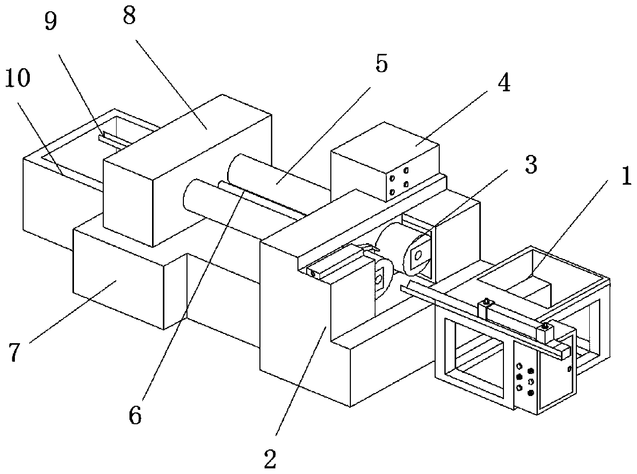
[0027] see Figure 1-7 , the present invention provides a technical solution: a screw thread rolling machine, including a feeding mechanism 1, one end of the feeding mechanism 1 is fixedly installed with a material storage box 11, and the upper end of the feeding mechanism 1 is fixedly installed with a blanking block 12, and the lower One end of the material stopper 12 close to the material storage box 11 is provided with a discharge channel 13, and the end of...


PUM


Abstract

The invention discloses a screw thread rolling machine. The machine comprises a feeding mechanism, wherein one end of the feeding mechanism is fixedly provided with a storage box, and falling stop blocks are fixedly arranged at the upper end of the feeding mechanism; discharging through grooves are formed in the ends, close to the storage box, of the falling stop blocks, a feeding channel is fixedly arranged at the end, away from the discharging through grooves, of the falling stop blocks, a feeding air cylinder is fixedly arranged on the feeding channel, and a discharging push block is fixedly arranged on the feeding air cylinder; and an electric control box is fixedly arranged on the outer side of the feeding mechanism, a maintenance door is movably arranged on the electric control box,a function key is fixedly arranged at the end, adjacent to the maintenance door, of the electric control box, and an adjusting knob is fixedly arranged on the outer side of the function key. According to the screw thread rolling machine, the feeding mechanism capable of automatic feeding is added, so that an operator can be liberated, only raw materials in the storage device are required to placeon the feeding mechanism, therefore the direct contact between the operator and the equipment is reduced, and the operator is better protected.

Description

technical field [0001] The invention relates to the technical field of screw processing, in particular to a screw rolling machine. Background technique [0002] The screw is a cylinder with spiral grooves cut on the outer surface or a cone cut with spiral grooves on the conical surface. At present, the commonly used screw materials in my country include No. 45 steel, 40Cr, ammoniated steel, 38CrMOAl, superalloy, etc., which are mostly used in plastic molding equipment. , such as plastic profile extruders, injection molding machines, etc. The screw and barrel are the core components of plastic molding equipment, the part that is heated, extruded and plasticized, and the core of plastic machinery. The thread rolling machine is a multifunctional cold extrusion machine. Forming machine tools and thread rolling machines can process thread, straight grain, and oblique grain rolling on workpieces in a cold state within the range of rolling force, rolling, straightening, diameter redu...

Claims


Application Information

Patent Timeline
Patent Type & Authority Applications(China)
IPC IPC(8): B21H3/04B21H9/02
CPCB21H3/044B21H9/02
Inventor 姜文国
Owner 浙江君悦标准件有限公司
Learn More