high performance gynecological forceps

A high-performance, gynecological technology, applied in the field of medical devices, can solve the problems of poor control of the gripping force of the fetal head, easy injury to the fetus and the mother, and achieve the effects of simple structure, safety and ease of use.

Inactive Publication Date: 2020-11-06
NANYANG CITY CENT HOSPITAL
View PDF14 Cites 0 Cited by
  • Summary
  • Abstract
  • Description
  • Claims
  • Application Information

AI Technical Summary

Problems solved by technology

The forceps in the prior art are not easy to control the clamping force of the fetal head, and it is easy to injure the fetus and the mother

Method used


Image

  • high performance gynecological forceps
  • high performance gynecological forceps
  • high performance gynecological forceps

Examples


Embodiment 1

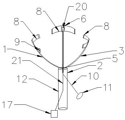
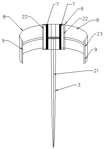
[0022] During specific implementation, a kind of high-performance gynecological forceps, such as figure 1 As shown, it includes a clamping part 1 and a tightening part 2 whose centers of gravity are on the same axis. The top edge of the tightening part 2 fits against the bottom outer wall of the clamping part 1. Three clamping rods 3 are distributed, and the clamping rods 3 are arc-shaped supports 4 bent upwards from the bottom, so that the three clamping rods 3 form a funnel shape, and the bottoms of the arc-shaped supports 4 are gathered and fixed at the joint 5 , the connection 5 is located on the central axis of the tightening part 2, the other end of the connecting part 5 is fixed with a pole 10, the other end of the pole 10 is fixed with a handle 11, the tightening part 2 The outer wall is provided with a handle 12, and a limit stop is provided between the joint 5 and the pole 10 to ensure that the joint 5 is always located on the central axis of the tightening part 2 wh...

Embodiment 2

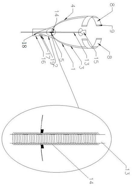
[0027] In another embodiment, a high-performance gynecological forceps, such as image 3 As shown, the difference from Example 1 is that the tightening part 2 is provided with two symmetrical clamping rods 3, the tightening part 2 is an inverted triangular pyramid, and the top of the tightening part 2 The edge fits against the outer wall of the bottom of the clamping part 1. The lower end of the tightening part 2 is connected with a handle part 16, and its bottom cone is embedded in the inside of the handle part 16. The clamping part 1, the tightening part 2, the handle The position of the center of gravity axis of the part 16 is provided with a shrink tube 13. The shrink tube 13 is made of hard material, the inside is hollow, and has a certain tensile strength. The bottom end of the clamping part 1 passes through the shrink tube 13. It is clamped with the tightening part 2, and the connection 5 between the shrink tube 13 and the clamping part 1 is provided with a correspondin...


PUM


Abstract

The invention belongs to the field of medical devices, and in particular relates to a high-performance gynecological forceps, which includes a clamping part, a tightening part, and a hand-holding part whose center of gravity is on the same axis. The top edge of the tightening part fits against the outer wall of the bottom of the clamping part. Rely, the lower end of the tightening part is connected with a handle part, and the clamping part includes several clamping rods distributed at equal intervals. The clamping rods are arc-shaped supports bent upwards from the bottom, and the arc-shaped supports The bottom of the arc support is gathered and fixed at the joint, the top of the arc support diverges, and a winding box is fixed radially embedded, and two winding shafts are arranged in the winding box, and the upper and lower ends of the winding shaft pass through The spring is fixedly connected with the winding box, the winding shaft is fixed with a coiled jacket, and the end of the jacket is provided with an electromagnetic induction part. The clamping part provided by the present invention can be contracted, and can shrink into a column before entering the birth canal, which is convenient for entering the birth canal. After touching the fetus, the clamping part can be manually diverged, which is easy to grasp the strength and will not hurt the fetus and the mother.

Description

technical field [0001] The invention belongs to the field of medical instruments, in particular to a high-performance gynecological forceps. Background technique [0002] Forceps are an instrument that can be used to assist a mother in delivering her baby. Forceps midwifery is one of the important means to solve cephalic dystocia, shorten the second stage of labor, and terminate pregnancy as soon as possible. In the prior art, the forceps consisted of two branches (blades) positioned around the fetal head. These branches are defined as left and right lobes depending on which side of the mother's pelvis they are applied to. Branches usually (but not always) cross at the midpoint of the joint. Most forceps have locking features at the joint, but a few have sliding features that allow the two branches to slide along each other. Forceps with a fixed locking structure are used for deliveries that require little or no rotation, such as when the fetal head is aligned with the m...

Claims


Application Information

Patent Timeline
Patent Type & Authority Patents(China)
IPC IPC(8): A61B17/44
CPCA61B17/442
Inventor 杨建敏
Owner NANYANG CITY CENT HOSPITAL
Why Eureka
Try Eureka