System and method for active cancellation of pressure pulses

A pressure and differential pressure technology, applied in the field of gas concentration measurement and monitoring, which can solve problems such as poor measurement accuracy

Active Publication Date: 2019-11-12
KONINKLJIJKE PHILIPS NV
View PDF22 Cites 0 Cited by
  • Summary
  • Abstract
  • Description
  • Claims
  • Application Information

AI Technical Summary

Problems solved by technology

If the sensor saturates, the low-pass method produces an error in the flow rate measurement, but unless a very expensive, high-accuracy sensor is chosen, choosing a sensor with a wide range (compared to the desired measurement) usually results in poor measurement accuracy
In addition, this technique allows unattenuated pressure pulsations to appear in the measurement area, causing errors in the gas concentration measurement

Method used


Image

  • System and method for active cancellation of pressure pulses
  • System and method for active cancellation of pressure pulses

Examples


Embodiment Construction

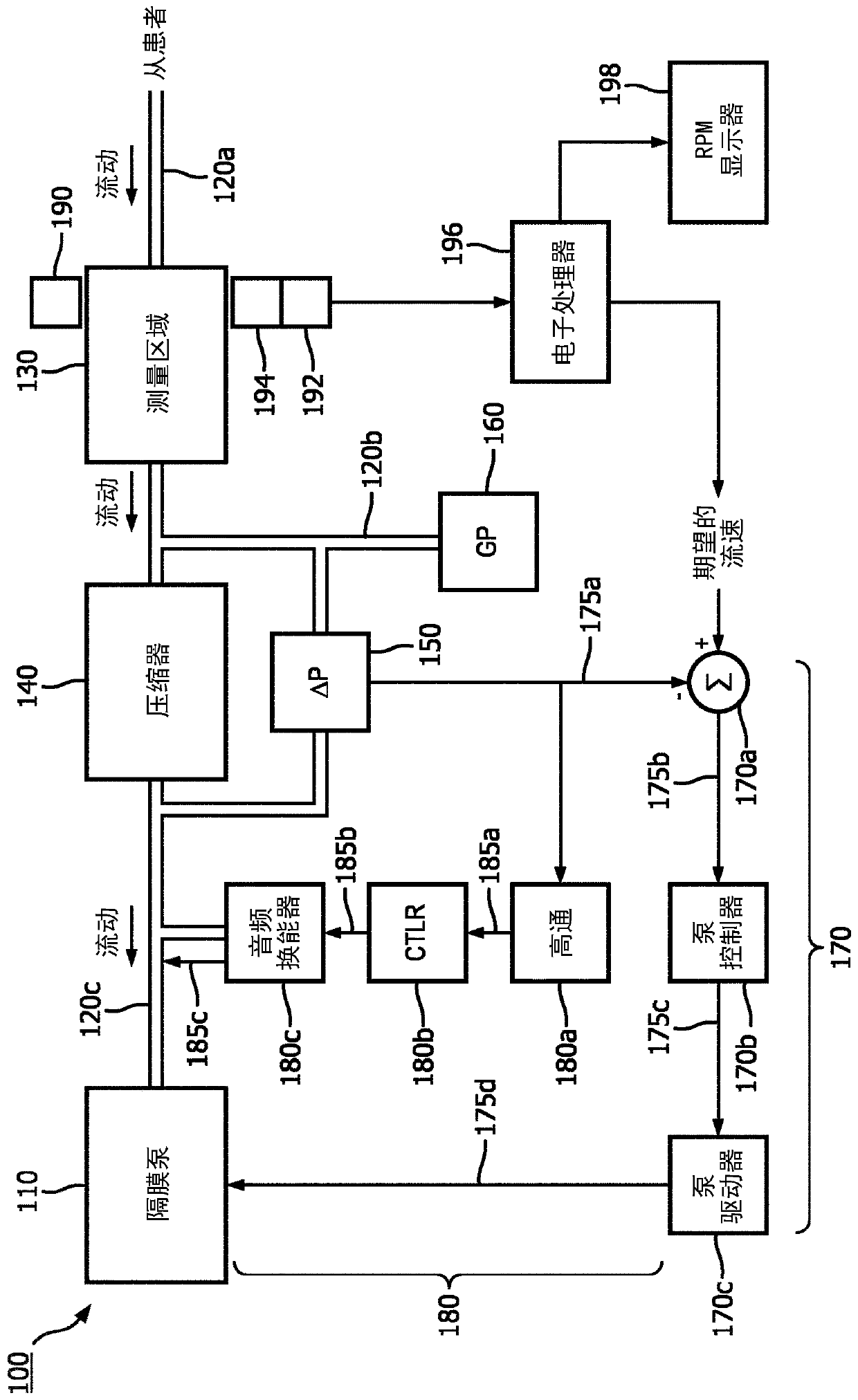
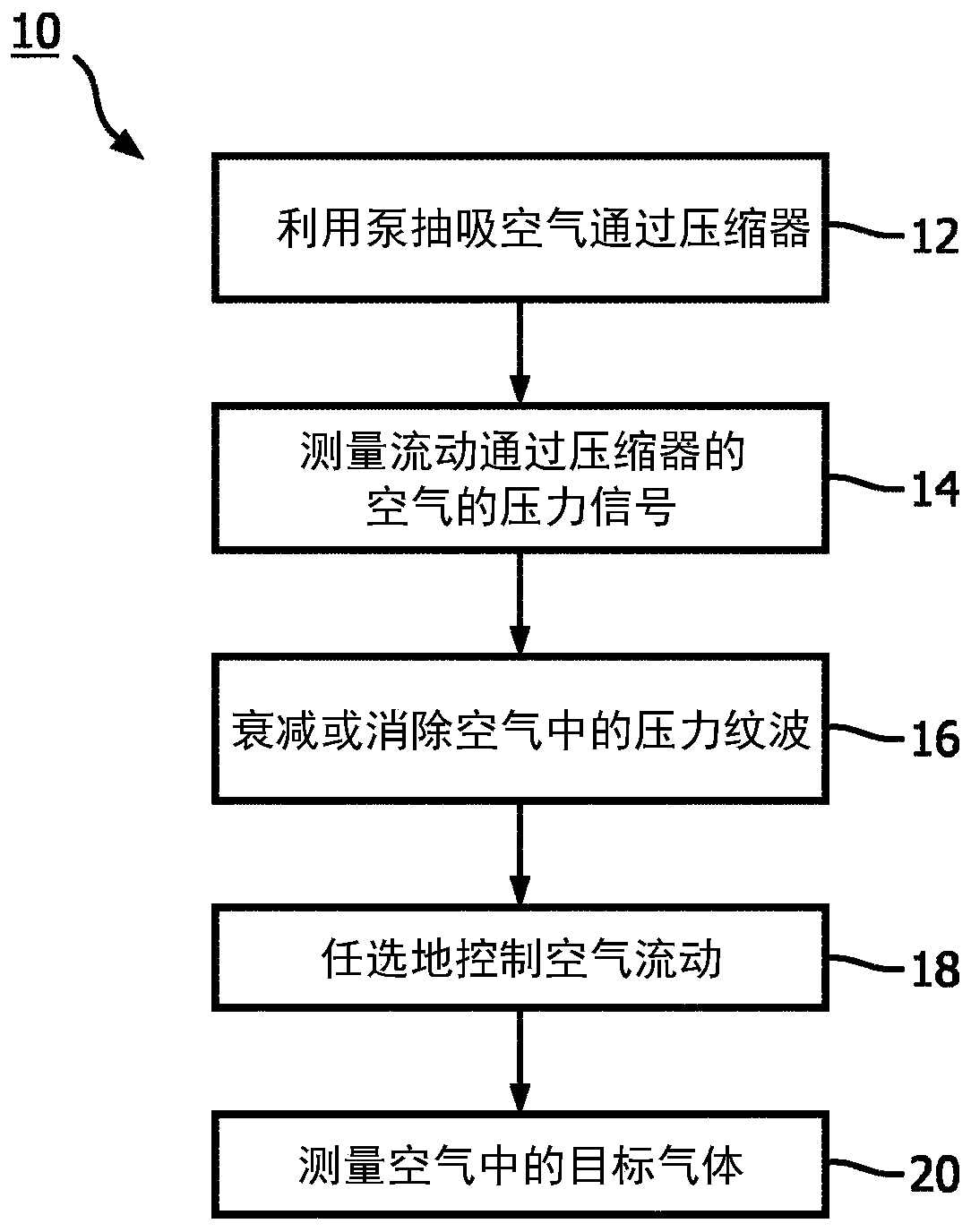
[0018] In RGM, the flow of breathing gas is usually regulated to a relatively constant rate to avoid transient distortions of the gas concentration record (ie, waveform). This flow regulation is often accomplished by introducing a compressor (such as an orifice or capillary) into the gas flow path and controlling the pump drive level to be controlled to maintain a constant pressure drop across the compressor. Since pressure drop is a direct function of flow rate, maintaining a constant pressure drop produces a constant flow rate. However, in the case of pump-induced pressure pulsations, the magnitude of the pulsations in the pressure drop can be large and can even exceed the magnitude of the flow-induced pressure drop, which can be problematic for the accuracy of flow rate measurement and control.

[0019] Another problem potentially introduced by pressure pulsations in the sample line is that pressure pulsations appear on the gas sample in the measurement region of the RGM. ...


PUM


Abstract

A respiration gas monitor device (100) includes a pump (110) connected to draw a flow of respired air, a pressure sensor (150, 160) is connected to measure an air pressure signal responsive to the flow of respired air, and a pressure transducer (180c). Electrical circuitry (170, 180) is operatively connected to measure flow across the pressure sensor. A gas component sensor (190, 192, 194) is arranged to monitor a target gas in the flow of respired air.

Description

technical field [0001] The following generally relates to the field of monitoring, the field of respiration, the field of pressure pulsation monitoring, the field of pressure pulsation cancellation, the field of gas concentration measurement and related fields. Background technique [0002] In a sidestream respiratory gas monitor (RGM) (also known as a diverted RGM), a sample of respiratory gas is drawn from the patient down the sample tube into the measurement area of ​​the RGM (Respiratory Gas Monitor), where various techniques Any of the techniques can be used to measure the concentration of one or more components of respiratory gases, including but not limited to: carbon dioxide (CO 2 ), oxygen (O 2 ), nitrous oxide (N 2 O) and halogenating agents such as halothane, enflurane, isoflurane, sevoflurane and desflurane. Patterns of change in the concentrations of these gas constituents may have clinical significance in the management of patients. Accordingly, it is desir...

Claims


Application Information

Patent Timeline
Patent Type & Authority Applications(China)
IPC IPC(8): A61B5/00A61B5/08A61B5/097
CPCA61B5/7203A61B5/0803A61B5/082A61B5/097A61B5/7225A61B2562/0233A61B2562/0247A61B5/0082A61B5/087
Inventor E·P·格雷蒂
Owner KONINKLJIJKE PHILIPS NV
Why Eureka
Try Eureka