
Optical fiber relay remote equipment

An optical fiber and equipment technology, applied in the field of communication equipment, can solve the problems of unsatisfactory call quality, large wall loss, long construction period, etc., and achieve the effect of being suitable for long-distance transmission, small optical fiber loss, and fast construction

Pending Publication Date: 2019-11-12
EVERTAC COMM TECH SHANGHAI
View PDF0 Cites 1 Cited by
  • Summary
  • Abstract
  • Description
  • Claims
  • Application Information

AI Technical Summary

Problems solved by technology

For environments such as high-rise buildings and large venues, due to the loss of feeders, power divider couplers and other sub-systems, the RF signal cannot effectively cover every area of ​​the building, resulting in unsatisfactory call quality in some areas inside the building; direct communication between walkie-talkies , limited by the transmission power and receiving sensitivity of the terminal, the communication distance is very limited. Due to the large wall loss of large buildings, it is still difficult for the conventional indoor distribution system to meet the coverage requirements in the case of large area coverage; at the same time, a large number of construction base stations can meet the requirements of public security, fire protection and The property has communication needs for high-rise buildings and large venues, but the investment in building base stations is large and the construction period is long, which is not cost-effective for some application scenarios with small traffic volumes

Method used


Image

  • Optical fiber relay remote equipment
  • Optical fiber relay remote equipment
  • Optical fiber relay remote equipment

Examples


Embodiment Construction

[0041] The following will clearly and completely describe the technical solutions in the embodiments of the present invention with reference to the accompanying drawings in the embodiments of the present invention. Obviously, the described embodiments are only some, not all, embodiments of the present invention. Based on the embodiments of the present invention, all other embodiments obtained by persons of ordinary skill in the art without creative efforts fall within the protection scope of the present invention.

[0042] It should be noted that, in the case of no conflict, the embodiments of the present invention and the features in the embodiments can be combined with each other.

[0043] The present invention will be further described below in conjunction with the accompanying drawings and specific embodiments, but not as a limitation of the present invention.

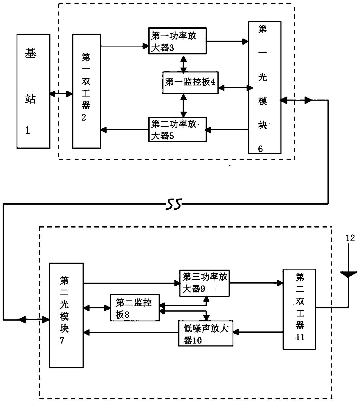
[0044] refer to figure 1 The working principle diagram of the optical fiber relay remote equipment provided by ...


PUM


Abstract

The invention relates to the technical field of communication equipment, in particular to optical fiber relay remote equipment, which comprises an optical fiber relay far-end machine and an optical fiber relay far-end machine, the optical fiber relay far-end machine realizes signal transmission with the optical fiber relay far-end machine through an optical cable; the optical fiber relay pull far-near end machine comprises a first duplexer, a first power amplifier, a second power amplifier, a first monitoring board and a first optical module. The optical fiber relay remote terminal comprises asecond duplexer, a third power amplifier, a low-noise amplifier, a second monitoring board and a second optical module; base station signals are output through the optical fiber relay remote device,then the signals are transmitted out through the retransmission antenna, and meanwhile the retransmission antenna can receive the signals transmitted by the interphone and transmit the signals to thebase station through the optical fiber relay remote device. Compared with a base station, the method has the advantages of low cost and fast construction, and is suitable for large-scale scenes.

Description

technical field [0001] The invention relates to the technical field of communication equipment, in particular to an optical fiber relay remote equipment. Background technique [0002] The longest communication distance of 1W walkie-talkies sold on the market is 5KM, and the communication distance for urban environments is far less than 5KM. For environments such as high-rise buildings and large venues, due to the loss of feeders, power divider couplers and other sub-systems, the RF signal cannot effectively cover every area of ​​the building, resulting in unsatisfactory call quality in some areas inside the building; direct communication between walkie-talkies , limited by the terminal transmit power and receive sensitivity, the communication distance is very limited. Due to the large wall loss of large buildings, it is still difficult for the conventional indoor distribution system to meet the coverage requirements in the case of large area coverage; at the same time, a lar...

Claims


Application Information

Patent Timeline
Patent Type & Authority Applications(China)
IPC IPC(8): H04B10/29H04B10/40H04L5/14H04B10/548
CPCH04B10/29H04B10/40H04L5/14H04B10/548
Inventor 张通赵禕博倪捷
Owner EVERTAC COMM TECH SHANGHAI
Learn More