Converter switch current decoupling circuit

A switching current and converter technology, applied in the electronic field, can solve problems such as unclear working process, complicated drawing, and inconvenient learning for beginners

Inactive Publication Date: 2019-11-12
NORTH CHINA UNIVERSITY OF TECHNOLOGY
View PDF2 Cites 1 Cited by
  • Summary
  • Abstract
  • Description
  • Claims
  • Application Information

AI Technical Summary

Problems solved by technology

[0005] Comparing the two description methods, it can be seen that the first method is used to describe the working process, and the turn-on process and the shutdown process are described separately. The working process is clear and easy to understand, but the drawing is complicated and must be described with two pictures; the second method is used Describe the working process, the turn-on process and the turn-off process are combined and described. Only one picture can describe the two working processes, but the working process is not clear enough and difficult to understand, especially for Cuk and Zeta converters, the conduction current The flow path of the flow path and the flow path of the shut-off current are mixed together, which brings a lot of inconvenience to beginners

Method used


Image

  • Converter switch current decoupling circuit
  • Converter switch current decoupling circuit
  • Converter switch current decoupling circuit

Examples


Embodiment 1

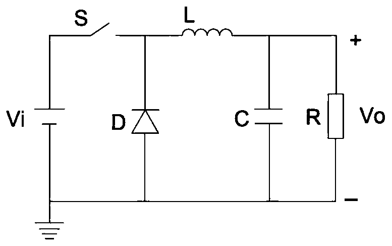
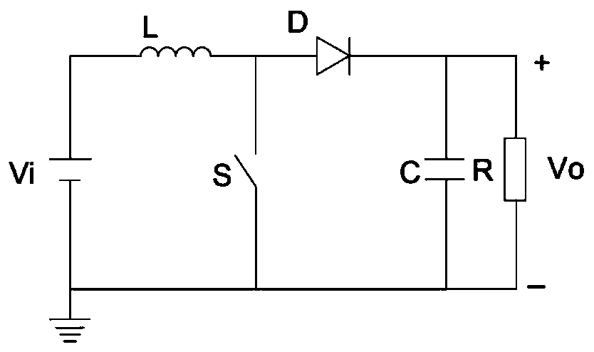
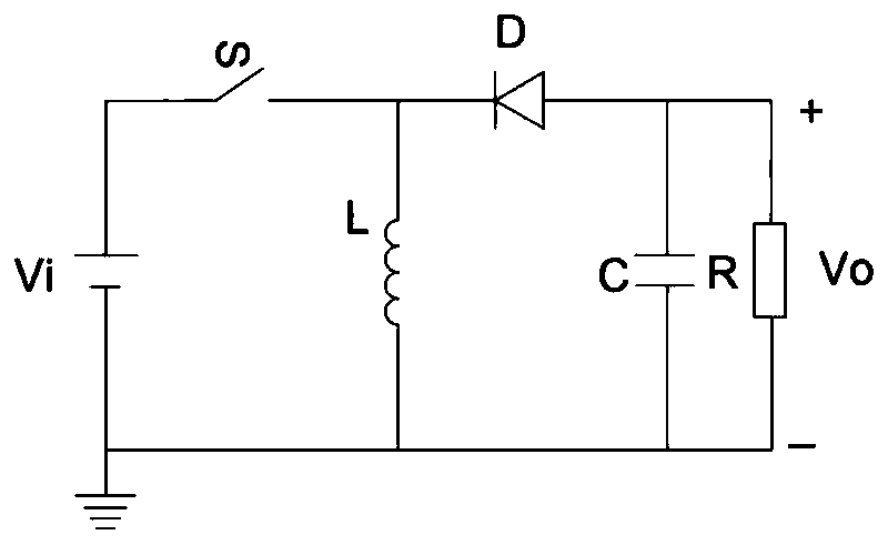
[0042]According to the basic theory of power electronics, the core and essence of power electronics technology is to complete the transformation of voltage and current through the high-frequency on and off of the switch tube and the energy storage and release of the energy storage element. Obviously, Buck, Boost, Buck-Boost, Cuk and Zeta converters are all controlled by a single transistor, which makes it possible to separate the switch-on current path and the switch-off current path. That is, the switching currents of the five basic DC-DC converters, Buck, Boost, Buck-Boost, Cuk and Zeta, can be decoupled.

[0043] Five basic DC-DC converter circuits can be divided into single-node and double-node according to the number of nodes. For Buck, Boost, and Buck-Boost converters, the converter switching current decoupling circuit, if the energy storage element is the center And the common branch, the switch current decoupling circuit is represented by separating the switch tube bra...


PUM


Abstract

The invention relates to a converter switch current decoupling circuit; for Buck, Boost and Buck-Boost converters, a switch current decoupling circuit is represented by taking an energy storage element as a center and a public branch, and with separated switch tube branch and diode branch; for Cuk and Zeta converters, if the branch circuit wherein an energy storage capacitor is located serves as the center branch of the circuit, the branch circuits where a first inductor and a first diode are located are arranged on the upper left and upper right of the central branch with an angle of 45 degrees; and branch circuits where a first switch tube and a second inductor are located are arranged on the lower left and lower right of the central branch with an angle of 45 degrees. Due to the adoption of the scheme, the circuit is simple and symmetrical, the physical process of energy storage and release of the energy storage element under the effect of the switch tube and the diode is achieved,the circuit is simple and easy to learn, and the circuit is a beneficial supplement of the existing basic DC-DC converter principle description.

Description

technical field [0001] The invention belongs to the field of electronics, in particular to an equivalent circuit of a converter. Background technique [0002] The existing basic DC-DC converters (including Buck, Boost, Buck-Boost, Cuk and Zeta) all adopt the power supply-switching unit-load description method in the circuit description, that is, the power supply supplies power to the load after being transformed by the switching unit. Such as Figure 1 to Figure 5 shown. Without loss of generality, taking Buck as an example, the power source is Vi, the switch tube S, diode D and inductor L together constitute the switching unit, the load is R, and C is the filter capacitor. [0003] The above circuits are all controlled by a single switch, so there are two working processes of the switch being turned on and the switch being turned off. There are two ways to describe the work process. Method 1 adopts the method of drawing circuit diagrams of the switching tube on-circuit a...

Claims


Application Information

Patent Timeline
IPC IPC(8): H02M1/00
CPCH02M1/00
Inventor 孟庆海刘林凯周京华闫皓月刘从伟刘欣博田浩
Owner NORTH CHINA UNIVERSITY OF TECHNOLOGY
Why Eureka
Try Eureka