PMU device for power distribution network

A technology of distribution network and electric power, which is applied in the directions of cable installation, circuit, transformer/reactor installation/support/suspension, etc. It can solve problems such as cumbersome installation and disassembly, unreliability, safety accidents, etc., and achieve cost and weight reduction , the effect of improving reliability

Pending Publication Date: 2019-11-12
苏州银蕨电力科技有限公司
View PDF0 Cites 0 Cited by
  • Summary
  • Abstract
  • Description
  • Claims
  • Application Information

AI Technical Summary

Problems solved by technology

[0004] Existing sensor devices use two or even three screws to realize the functions of opening, closing and locking the power line of the device, or use a combination of hinges and screws to realize this function; not only increases the cost and weight of the device, And it will cause cumbersome and unreliable installation and disassembly, and even cause safety accidents

Method used


Image

  • PMU device for power distribution network
  • PMU device for power distribution network
  • PMU device for power distribution network

Examples


Embodiment

[0044] Such as Figure 1 to Figure 8 as shown,

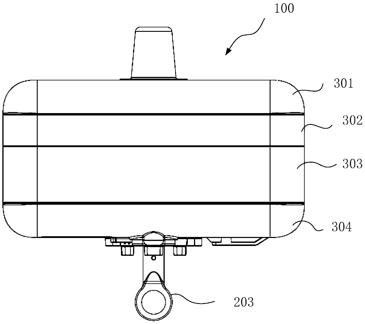
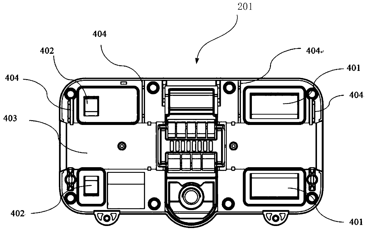
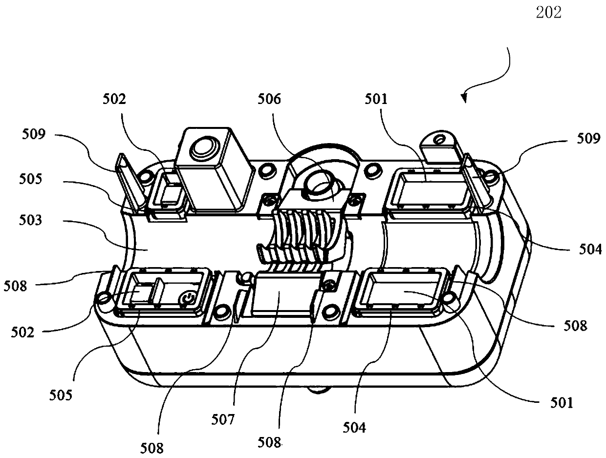
[0045] A distribution network PMU device, including a housing 100 and an electronic circuit board built in the housing, the housing 100 is provided with a cavity, and the housing includes an upper housing and a lower housing that can be separated from each other body, the cavity includes a first cavity 201 and a second cavity 202 which are relatively separately arranged in the upper casing and the lower casing, and the first cavity 201 and the second cavity 202 are respectively There are an upper semi-cylindrical groove 403 and a lower semi-cylindrical groove 503, which are arranged correspondingly and located on the axis. The first cavity 201 and the second cavity 202 are also equipped with current transformers , respectively set on the left and right sides of the first cavity 201 and the second cavity 202, the current transformer is electrically connected with the electronic circuit board; it also includes an opening and clos...


PUM


Abstract

The invention relates to a PMU device for a power distribution network. The PMU device includes a casing and an electronic circuit board built in the casing. A cavity is arranged in the casing. The casing includes an upper casing and a lower casing that can be separated from each other. The cavity comprises a first cavity and the second cavity that are arranged opposite to each other in the uppercasing and the lower casing in a separate manner. The first cavity and the second cavity are respectively provided with an upper semi-cylinder groove and a lower semi-cylinder groove. The first cavityand the second cavity are further provided with current transformers; the PMU device further includes an open-close locking mechanism. By twisting an open-close screw rod, the device disclosed in theinvention can be rapidly opened and closed in stalling and dismounting processes; by operating a special purpose insulating operation rod, the PMU device can be quickly installed on a 380V-35kV powerline in an electrified and equipotential manner.

Description

technical field [0001] The invention relates to a distribution network PMU device. Background technique [0002] The existing medium and low voltage power distribution overhead lines (380V-35kV) are fault-prone lines, and a large number of sensing devices are required to monitor the lines and locate faults. Due to issues such as power grid operation costs and grid operation safety, it is necessary for the sensing device to be installed safely, conveniently and quickly at the measurement position required by the power line, and to ensure that locking the power line will not cause accidents such as rotation, sideslip, or even falling of the device itself. . In the vast majority of installation situations, it is required that the sensing device can be installed or disassembled without power failure of the power grid, which requires the sensing device to be able to safely and quickly realize the opening and hooking of the power line from the device by using an insulated operati...

Claims


Application Information

Patent Timeline
Patent Type & Authority Applications(China)
IPC IPC(8): H01F27/06H01F27/02H01F27/04H01F27/23H01F38/30H01F38/14H02G7/00
CPCH01F27/02H01F27/04H01F27/06H01F27/23H01F38/14H01F38/30H02G7/00
Inventor 倪贵成傅岳林罗治军张斌
Owner 苏州银蕨电力科技有限公司
Why Eureka
Try Eureka