
Precise adjustable optical fiber coupler

An optical fiber coupler and optical fiber technology, which is applied in the field of precision adjustable optical fiber couplers, can solve the problems of non-adjustable coupling ratio, limited adjustable precision, and difficult to control coupling ratio, and achieves wide working wavelength range, low cost, and coupling efficiency. high effect

Inactive Publication Date: 2019-11-12
FUZHOU OPTOWIDE TECH CO LTD
View PDF8 Cites 0 Cited by
  • Summary
  • Abstract
  • Description
  • Claims
  • Application Information

AI Technical Summary

Problems solved by technology

The current fiber coupler has technical problems that the coupling ratio is not easy to control, the coupling ratio cannot be adjusted, or the adjustable accuracy is limited.

Method used


Image

  • Precise adjustable optical fiber coupler

Examples


Embodiment 1

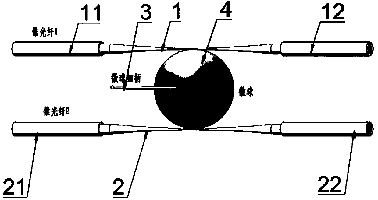
[0014] Such as figure 1 As shown, this embodiment provides a precision adjustable fiber coupler, including a first tapered fiber 1, a second tapered fiber 2, a thin handle 3 and a microsphere 4, and the first tapered fiber 1 includes a first port 11 and The second port 12, the second tapered fiber 2 includes a third port 13 and a fourth port 14, wherein the first tapered fiber 1 and the second tapered fiber 2 are located on opposite sides of the microsphere 4, And the thin handle 3 is fixed on the microsphere 4, the second tapered optical fiber 2 is tangent to the microsphere 4, the second tapered optical fiber 2 and the microsphere 4 maintain a fixed position, and the The second tapered optical fiber 2 maintains a vertical relationship with the thin handle 3, the first tapered optical fiber 1 is tangent to the microsphere 4, and the positions of the first tapered optical fiber 1 and the microsphere 4 are not fixed. And the contact positions of the first tapered fiber 1 and t...

Embodiment 2

[0017] Such as figure 1 As shown, this embodiment provides a precision adjustable fiber coupler, including a first tapered fiber 1, a second tapered fiber 2, a thin handle 3 and a microsphere 4, and the first tapered fiber 1 includes a first port 11 and The second port 12, the second tapered fiber 2 includes a third port 13 and a fourth port 14, wherein the first tapered fiber 1 and the second tapered fiber 2 are located on opposite sides of the microsphere 4, And the thin handle 3 is fixed on the microsphere 4, the second tapered optical fiber 2 is in contact with the microsphere 4, the second tapered optical fiber 2 and the microsphere 4 maintain a fixed position, and the The second tapered optical fiber 2 maintains a vertical relationship with the thin handle 3, the first tapered optical fiber 1 is in contact with the microsphere 4, and the positions of the first tapered optical fiber 1 and the microsphere 4 are not fixed. And the first tapered optical fiber 1 is kept para...


PUM


Abstract

The invention discloses a precise adjustable optical fiber coupler. The precise adjustable optical fiber coupler comprises a first tapered optical fiber, a second tapered optical fiber, a fine handleand a microsphere, wherein the first tapered optical fiber comprises a first port and a second port; the second tapered optical fiber comprises a third port and a fourth port; the first tapered optical fiber and the second tapered optical fiber are located on two opposite sides of the microsphere; the fine handle is fixed on the microsphere; the second tapered optical fiber is in contact with themicrosphere; the second tapered optical fiber and the microsphere keep fixed positions; the second tapered optical fiber keeps a vertical relationship with the fine handle; the first tapered optical fiber is in contact with the microsphere; and the positions of the first tapered optical fiber and the microsphere are not fixed. The precise adjustable optical fiber coupler is high in coupling efficiency and the coupling proportion thereof can be precisely adjusted; at the interval of a free spectral range, the precise adjustable optical fiber coupler has a working wavelength and can be matched with a wavelength division multiplexing technology for use; and the precise adjustable optical fiber coupler is wide in working wavelength range, simple in process, low in cost and easy to realize industrial mass production.

Description

technical field [0001] The invention belongs to the technical field of optical fiber couplers, and in particular relates to a precision adjustable optical fiber coupler. Background technique [0002] The optical fiber coupler is an optical device that realizes the distribution or combination of optical signal power among different optical fibers. It is composed of the mutual exchange of guided wave energy in the core region of different optical fibers adjacent to the optical fiber surface. According to the type of optical fiber used, it can be divided into multimode optical fiber, Single mode fiber and polarization maintaining fiber coupler etc. For a waveguide fiber coupler, it is generally a component with a Y-shaped branch, which can be used to divide the optical signal input by an optical fiber into equal parts. When the opening angle of the coupler branch increases, the leakage into the cladding The light will increase so that the excess loss is increased, so the openi...

Claims


Application Information

Patent Timeline
Patent Type & Authority Applications(China)
IPC IPC(8): G02B6/38
CPCG02B6/3841G02B6/3873
Inventor 彭隆祥刘成林周敢
Owner FUZHOU OPTOWIDE TECH CO LTD
Learn More