A cable bonding device

A technology for cables and appliances, applied in the field of cable splicing appliances, can solve the problems of wasting more time, rising costs, and prolonging the progress of cable construction projects, and achieves the effects of strong functionality, prolonged progress, complete moisture resistance and insulation performance.

Active Publication Date: 2020-06-19
上海闸电东海电力工程有限公司
View PDF5 Cites 0 Cited by
  • Summary
  • Abstract
  • Description
  • Claims
  • Application Information

AI Technical Summary

Problems solved by technology

[0002] The cable is made of one or more mutually insulated conductors and the entire outer surface is covered with a highly insulating covering layer. It is a wire that transmits power or information from one place to another. After the cable is laid, in order to make it a For a continuous line, each section of the line must be connected as a whole. At this time, it is necessary to overlap the segmented cables so that the cables of each section are connected to each other to form a whole. The cable overlapping method is usually manual. Cable connection needs to go through many steps, the operation is relatively complicated, and operators with certain experience are required to complete the cable lapping work, resulting in a waste of time in cable lapping, prolonging the progress of cable construction projects and increasing costs , so it is necessary to develop a new type of convenient and stable cable lapping device, in order to solve the problem that manual lapping cables need to go through many steps, the operation is relatively complicated, and operators with certain experience are required to complete the cable lapping work. As a result, a lot of time is wasted in cable bonding, which prolongs the progress of the cable construction project and increases the cost.

Method used


Image

  • A cable bonding device
  • A cable bonding device
  • A cable bonding device

Examples


specific Embodiment approach

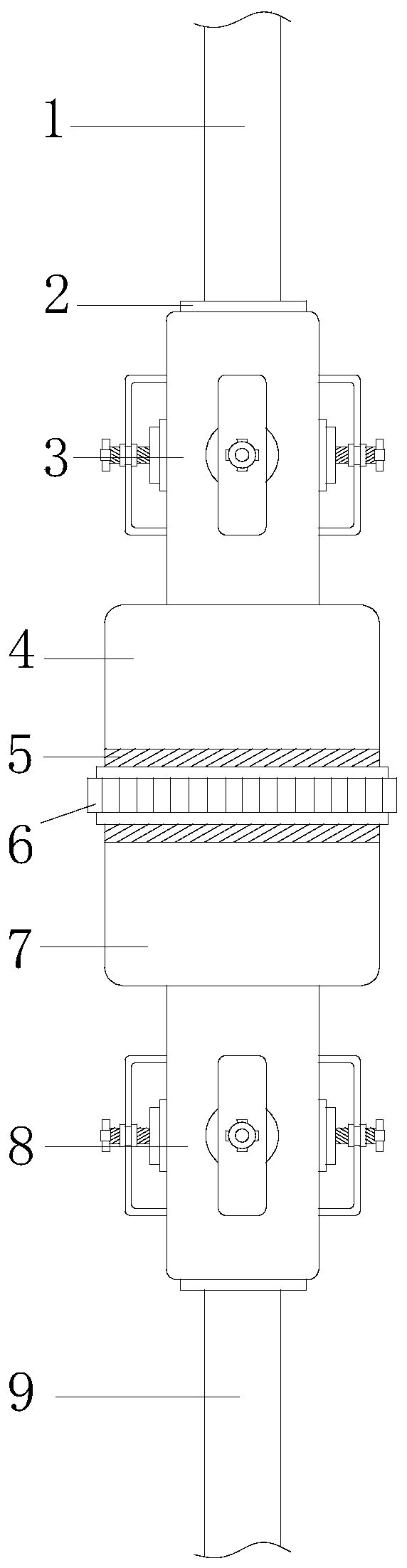
[0028] see figure 1, a cable lapping device, its structure includes a first cable 1, a sealing ring 2, an upper cable locking sleeve 3, an upper conductor connecting sleeve 4, a thread groove 5, a locking spiral ring 6, a lower conductor connecting sleeve 7. The lower cable locking sleeve 8, the second cable 9, the upper conductor connecting sleeve 4 is provided with a threaded groove 5, the upper conductor connecting sleeve 4 is provided with a locking screw ring 6, the described The locking screw ring 6 and the thread groove 5 are threaded, and the upper conductor connecting sleeve 4 and the lower cable locking sleeve 8 are connected through the locking screw ring 6, and the upper and lower ends of the locking screw ring 6 are respectively An upper cable locking sleeve 3 and a lower cable locking sleeve 8 are provided, and the upper cable locking sleeve 3 and the lower cable locking sleeve 8 have an axisymmetric structure, and the upper cable locking sleeve 3 is installed ...


PUM


Abstract

The invention discloses a cable lap joint fitting. The structure of the cable lap joint fitting comprises a first cable, a seal ring, an upper cable locking sleeve, an upper conductor connecting sleeve, a threaded groove, a locking screw ring, a lower conductor connecting sleeve, a lower cable locking sleeve and a second cable. The cable lap joint fitting is composed of the seal ring, the upper cable locking sleeve, the upper conductor connecting sleeve, the lower conductor connecting sleeve and the lower cable locking sleeve, can complete lap joint operation of the first cable and the secondcable through simple operation and locking to integrate the first cable and the second cable to a whole, and has complete moisture-proof and insulation properties to solve the problems that the manuallap joint of the cables needs multiple steps, is relatively complex in operation and requires operators with a certain experience to complete the lap joint of the cables to cause waste of a lot of time at the aspect of lap joint of the cables, prolong the cable construction engineering progress and improve the cost.

Description

technical field [0001] The invention relates to the field of cables, in particular to a cable lapping device. Background technique [0002] The cable is made of one or more mutually insulated conductors and the entire outer surface is covered with a highly insulating covering layer. It is a wire that transmits power or information from one place to another. After the cable is laid, in order to make it a For a continuous line, each section of the line must be connected as a whole. At this time, it is necessary to overlap the segmented cables so that the cables of each section are connected to each other to form a whole. The cable overlapping method is usually manual. Cable connection needs to go through many steps, the operation is relatively complicated, and operators with certain experience are required to complete the cable lapping work, resulting in a waste of time in cable lapping, prolonging the progress of cable construction projects and increasing costs , so it is ne...

Claims


Application Information

Patent Timeline
IPC IPC(8): H02G15/18
CPCH02G15/18
Inventor 陈志宏
Owner 上海闸电东海电力工程有限公司
Why Eureka
Try Eureka